Solar panels
|
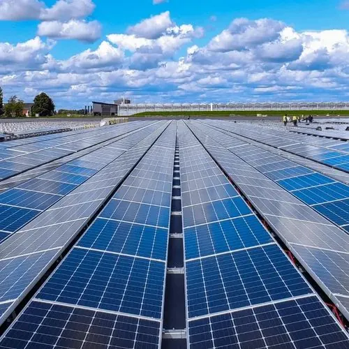
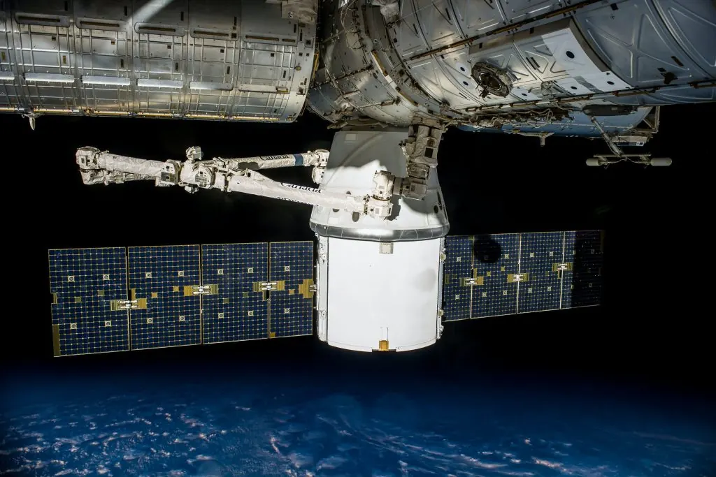
Solar power offers a sustainable way to generate electricity directly from sunlight, making it a useful source of energy for many electronic projects. It is nevertheless, not any form of magic, rather governed by laws of physics to dictate its performance and limitation. In this chapter, we will discuss how solar panels generate electric potential difference and the need of battery management system in projects.
|
 |
Semiconductors
|
A solar panel, also known as a photovoltaic (PV) cell, operates on the principle known as the photovoltaic effect. This occurs when a materials, called semiconductors, absorb light energy. Semiconductors, such as silicon, have electrical properties that fall between those of conductors and insulators.
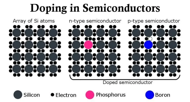
In its pure, crystalline form, silicon acts as an insulator because all its electrons are bound in covalent bonds with neighboring atoms. However, semiconductors can be intentionally modified through a process called "doping." By introducing specific impurity atoms, we can create two distinct types of silicon: n-type and p-type. N-type semiconductor is created by adding atoms, like phosphorus, that have an extra electron. This provides free, negatively charged electrons that can move through the material. P-type semiconductor is created by adding atoms, like boron, that have one less electron. This creates "holes," which are the absence of an electron and act as positive charge carriers. |
 |
Diode - A One Way Gate
The key to the photovoltaic effect is the junction where these n-type and p-type materials meet, known as the p-n junction. At this boundary, free electrons from the n-type side diffuse into the p-type side to fill some of the holes, and vice-versa. This movement creates a region near the junction that becomes depleted of free charge carriers, known as the "depletion zone." This zone is not neutral; it becomes electrically charged, establishing a built-in electric field. The n-type side gains a slight positive charge, and the p-type side gains a slight negative charge.
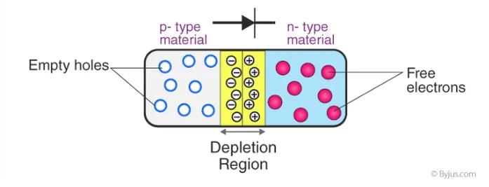
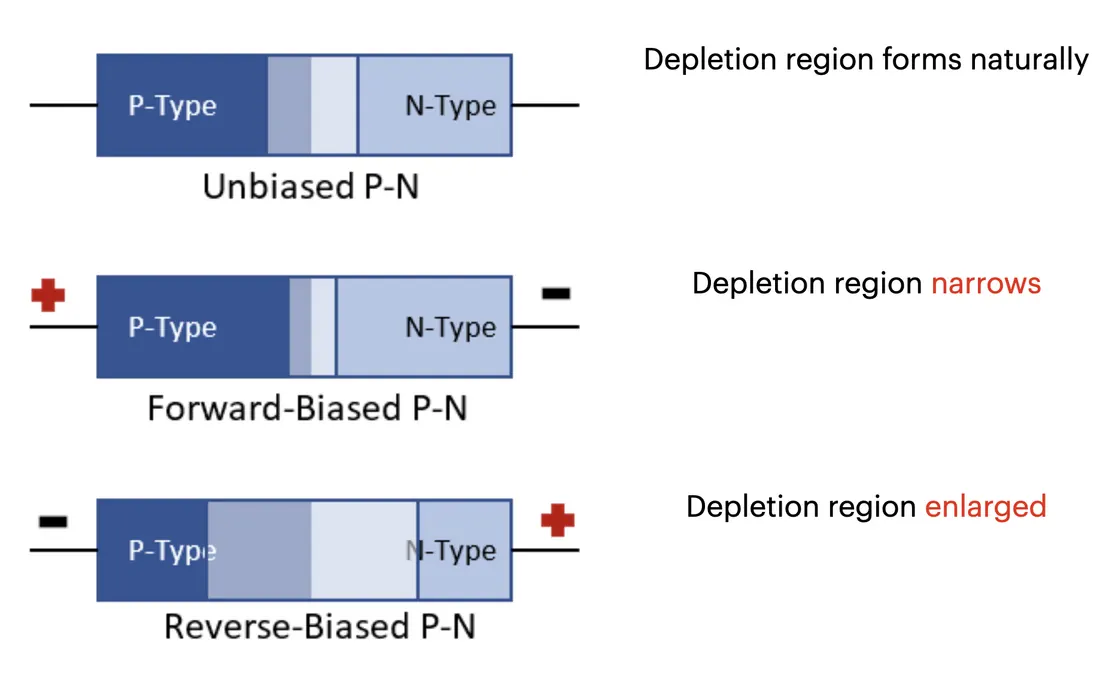
- When a voltage is applied in "forward bias" (positive to p-side, negative to n-side), it reduces the internal electric field. This causes the depletion zone to shrink, lowering the energy barrier and allowing a significant current to flow across the junction.
- Conversely, when a voltage is applied in "reverse bias" (positive to n-side, negative to p-side), it strengthens the internal electric field. This causes the depletion zone to enlarge, raising the energy barrier and effectively blocking the flow of current.
This electric field acts as a one-way barrier, allowing electrons to move from the p-side to the n-side, but not the other way. This property makes the p-n junction act as a one-way gate for electrical current, know as a Diode.
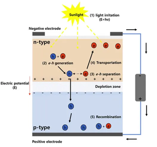
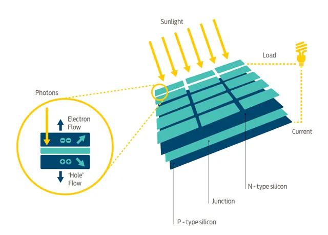
When a photon with sufficient energy strikes a pn junction, the energy is absorbed and creates an electron-hole pair. If this occurs within or near the depletion zone, where the region's inherent electric field acts swiftly, separating the charges by propelling the electron toward the n-side and the hole toward the p-side.
The separated charges now accumulate on their respective sides—electrons on the n-side and holes on the p-side. This creates a potential difference, or a voltage, across the junction, known as the photovoltaic voltage. If you connect the n-side and p-side with an external wire, you provide a path for these accumulated charges to flow. The electrons, which were pushed to the n-side, will now flow through the external wire back to the p-side to recombine with holes. This flow of electrons through the external circuit is the usable electricity.
The separated charges now accumulate on their respective sides—electrons on the n-side and holes on the p-side. This creates a potential difference, or a voltage, across the junction, known as the photovoltaic voltage. If you connect the n-side and p-side with an external wire, you provide a path for these accumulated charges to flow. The electrons, which were pushed to the n-side, will now flow through the external wire back to the p-side to recombine with holes. This flow of electrons through the external circuit is the usable electricity.
 |
 |
Solar Power Management System for small projects
A common question is why a solar panel cannot be connected directly to a load, such as a motor or an LED. The reason is that the electrical output from a solar panel is inconsistent. It varies with the intensity of sunlight; on a cloudy day or in the shade, the voltage and current produced can drop significantly. A direct connection would mean the connected device would operate intermittently and often below its required performance level. Furthermore, many electronic components, including microcontrollers like the Arduino, require a specific, stable voltage to function correctly, which a solar panel alone cannot reliably provide.
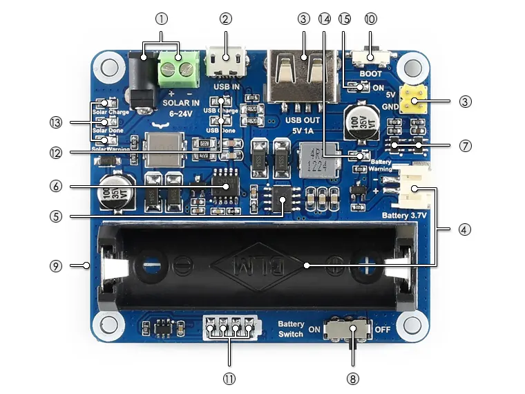
- Solar panel charging input: charged by solar panel, DC-002 jack or screw terminal
- USB charging input: charged by USB connection, connect a 5V power adapter through the Micro USB port
- 5V/1A power output: provides regulated 5V/1A output, USB port or 2.54mm pinheader
- Battery interfaces: for connecting 3.7V rechargeable Li battery, PH2.0 connector or 14500 battery holder
- CS8501: USB power management chip, for USB charging and 5V/1A boost output
- CN3791: solar power management chip, for solar panel charging and buck input
- Li battery protection chip: Li battery over charge / over discharge protection
- Battery switch
- MPPTSET switch (bottom side): supported level: 6V/9V/12V/18V/24V select the level closed to input level to improve charging efficiency
- BOOT key
- Battery capacity indicators
- USB charging indicators: USB Charge: on when USB charging USB Done: on when the battery is full charged by USB
- Solar panel charging indicators: Solar Charge: on when solar panel charging Solar Done: on when the battery is full charged by solar panel Solar Warning: on when solar panel reverse connection
- Battery warning: on when battery reverse connection
- Power output indicator: 5V/1A output
To create a reliable system, a solar power manager, often called a charge controller or power management circuit, is used. This electronic component acts as an intermediary between the solar panel, a battery, and the load.
The core function of a solar power manager is regulation. It takes the variable voltage from the solar panel and converts it to a stable voltage suitable for charging the battery and powering the load. This is often done using a DC-to-DC converter circuit. This regulation is important because a battery requires a specific voltage range for safe and efficient charging. Applying an unregulated voltage can lead to overcharging, which can permanently damage the battery and create a safety hazard. The power manager monitors the battery's charge level and adjusts or stops the charging process when the battery is full.
Additionally, many power managers include low-voltage disconnect features. This means they automatically disconnect the load from the battery if the battery's charge drops too low, preventing damage from over-discharging.
In summary, a complete solar-powered system for an Arduino project involves three main parts: the solar panel for energy generation, the battery for energy storage, and the solar power manager. The power manager coordinates the energy flow, ensuring the battery is charged safely and the connected devices receive stable power, thereby making effective use of the intermittent energy provided by the sun.
The core function of a solar power manager is regulation. It takes the variable voltage from the solar panel and converts it to a stable voltage suitable for charging the battery and powering the load. This is often done using a DC-to-DC converter circuit. This regulation is important because a battery requires a specific voltage range for safe and efficient charging. Applying an unregulated voltage can lead to overcharging, which can permanently damage the battery and create a safety hazard. The power manager monitors the battery's charge level and adjusts or stops the charging process when the battery is full.
Additionally, many power managers include low-voltage disconnect features. This means they automatically disconnect the load from the battery if the battery's charge drops too low, preventing damage from over-discharging.
In summary, a complete solar-powered system for an Arduino project involves three main parts: the solar panel for energy generation, the battery for energy storage, and the solar power manager. The power manager coordinates the energy flow, ensuring the battery is charged safely and the connected devices receive stable power, thereby making effective use of the intermittent energy provided by the sun.