Introduction to Buzzers
|
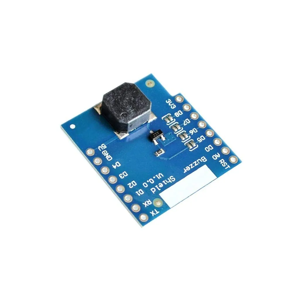
Audio feedback is a common way for electronic devices to communicate information. In Arduino projects, this is often achieved using small sound-emitting components called piezoelectric buzzers.
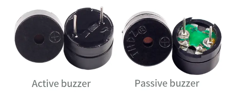
These devices produce sound through the vibration of a thin metal film. Inside the buzzer, a coil of wire surrounds a magnet. When electrical current passes through the coil, it creates a magnetic field that causes the metal film to vibrate rapidly, generating sound waves. There are two primary types of these buzzers: active and passive, which differ in their internal design and how they are controlled.
|
  |
Active buzzers
|
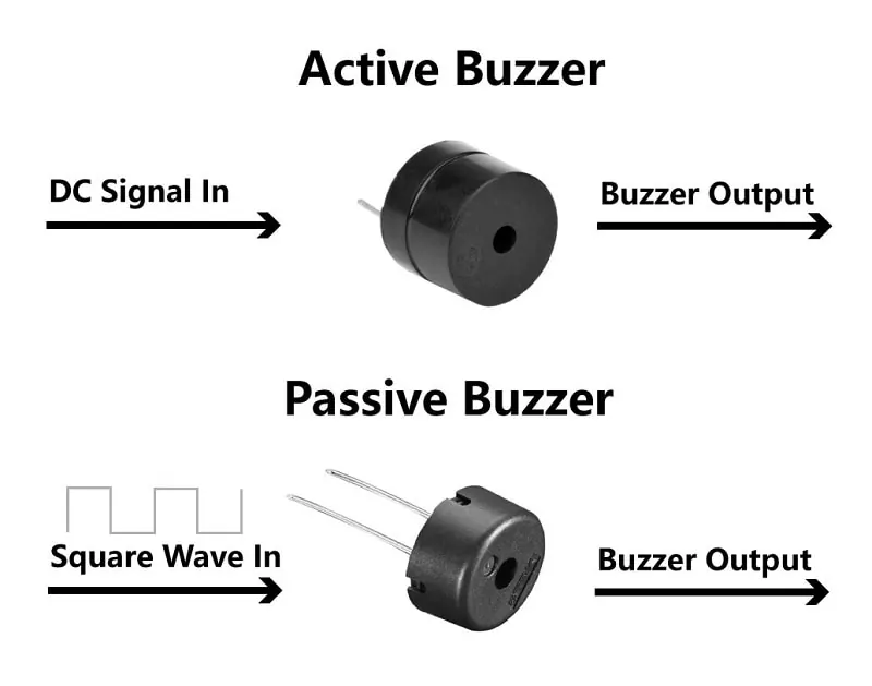
An active buzzer contains an internal oscillating circuit that produces a fixed frequency tone when a DC voltage is applied. This makes it straightforward to use, as simply connecting it to a power source will generate a continuous sound. In Arduino circuits, active buzzers are typically connected to digital pins and controlled like basic output devices.
This code uses digitalWrite() to turn the buzzer on and off. When the button is pressed (LOW state), the buzzer pin is set HIGH, producing sound. When the button is released, the pin is set LOW, stopping the sound. |
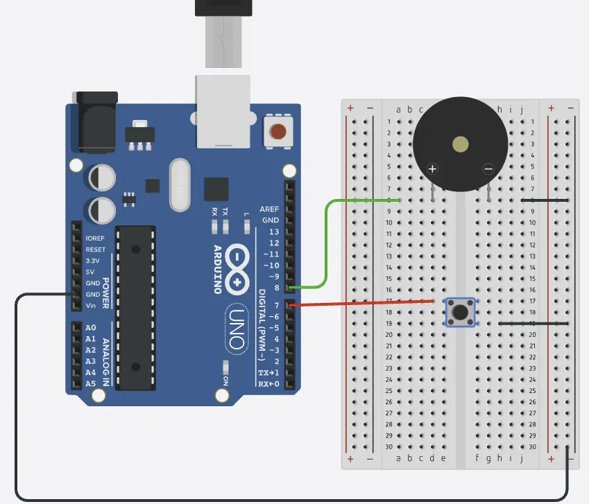 Click the image for the simulation
|
Button-Controlled Buzzer
int buzzerPin = 8;
int buttonPin = 7;

void setup() {
  pinMode(buzzerPin, OUTPUT);
  pinMode(buttonPin, INPUT_PULLUP);
}

void loop() {
  int buttonState = digitalRead(buttonPin);

  if (buttonState == LOW) {
    digitalWrite(buzzerPin, HIGH);
  } else {
    digitalWrite(buzzerPin, LOW);
  }
}
Exercise #1
Try to reverse logic of code above and let buzzer to be constantly "ON" and stop only when button is pressed and held.
Try to reverse logic of code above and let buzzer to be constantly "ON" and stop only when button is pressed and held.
Active buzzer with frequency control
However, if we were to control the frequency in an active buzzer, it requires some clever tricks involving the use delay() between on and off states.
The following code creates an Arduino program that controls a buzzer to generate two different frequencies, which can be toggled using a push button. The program initializes with the first frequency (100 Hz) active and continuously checks if the button is pressed; when pressed, it switches to the second frequency (166 Hz) and vice versa. The frequencies are generated by creating square waves with specific delay periods—5 milliseconds for the first frequency and 3 milliseconds for the second—each repeated 10 times per loop cycle to produce audible tones. A 300-millisecond delay after button detection helps prevent multiple toggles from a single press, and the use of the Arduino's internal pull-up resistor simplifies the button wiring by eliminating the need for an external resistor.
However, if we were to control the frequency in an active buzzer, it requires some clever tricks involving the use delay() between on and off states.
The following code creates an Arduino program that controls a buzzer to generate two different frequencies, which can be toggled using a push button. The program initializes with the first frequency (100 Hz) active and continuously checks if the button is pressed; when pressed, it switches to the second frequency (166 Hz) and vice versa. The frequencies are generated by creating square waves with specific delay periods—5 milliseconds for the first frequency and 3 milliseconds for the second—each repeated 10 times per loop cycle to produce audible tones. A 300-millisecond delay after button detection helps prevent multiple toggles from a single press, and the use of the Arduino's internal pull-up resistor simplifies the button wiring by eliminating the need for an external resistor.
Frequency-Toggle Buzzer
int buzzer = 8;
int buttonPin = 7;
bool useFirstFrequency = true;

void setup(){
  pinMode(buzzer, OUTPUT);
  pinMode(buttonPin, INPUT_PULLUP);
}

void loop(){
  // Check button state
  if (digitalRead(buttonPin) == LOW) {
    // Button is pressed - toggle frequency
    useFirstFrequency = !useFirstFrequency;
    delay(300); // Simple debounce delay
  }

  if (useFirstFrequency) {
    // First frequency: 100 Hz
    for(int i = 0; i < 10; i++){
      digitalWrite(buzzer, HIGH);
      delay(5);  // 5ms HIGH
      digitalWrite(buzzer, LOW);
      delay(5);  // 5ms LOW
    }
  } else {
    // Second frequency: ~166 Hz
    for(int i = 0; i < 10; i++){
      digitalWrite(buzzer, HIGH);
      delay(3);  // 3ms HIGH
      digitalWrite(buzzer, LOW);
      delay(3);  // 3ms LOW
    }
  }
}
Exercise #2
Modify the code to include a third frequency that cycles along with the existing two when the button is pressed. Adjust the timing delays to achieve this new frequency and ensure the button toggles through all three options in sequence (Frequency 1 → Frequency 2 → Frequency 3 → back to Frequency 1).
Passive Buzzer
A passive buzzer requires an external alternating signal to produce sound and lacks an internal oscillator. When tested with a DC source, it typically makes only a brief clicking sound. The advantage of passive buzzers is their ability to generate different tones and melodies by varying the input signal frequency. This makes them suitable for projects requiring multiple tones or simple musical sequences.
The Arduino tone() function generates square waves at specific frequencies to control passive buzzers. The basic syntax is:
The Arduino tone() function generates square waves at specific frequencies to control passive buzzers. The basic syntax is:
Tone Function Reference
tone(pin, frequency);
tone(pin, frequency, duration);
noTone(pin);
|
Here is example code that plays a musical scale. It cycles through seven musical notes (A to G) with one-second durations. The tone() function generates each frequency, while delay() controls the note duration. The noTone() function creates a one-second silence between repetitions.
|
 |
Musical Scale Buzzer
int buzzerPin = 8;

void setup() {
  pinMode(buzzerPin, OUTPUT);
  tone(buzzerPin, 1000, 2000); // Startup tone
}

void loop() {
  int notes[] = {440, 494, 523, 587, 659, 698, 784}; // Frequencies for A-G
  for (int i = 0; i < 7; i++) {
    tone(buzzerPin, notes[i]);
    delay(1000);
  }
  noTone(buzzerPin);
  delay(1000);
}
Exercise#3
Provided that
C4: 262 Hz | D4: 294 Hz | E4: 330 Hz | F4: 349 Hz | G4: 392 Hz | A4: 440 Hz | B4: 494 Hz |
C5: 523 Hz | D5: 587 Hz | E5: 659 Hz | F5: 698 Hz | G5: 784 Hz | A5: 880 Hz | B5: 988 Hz |
C6:1047 Hz|
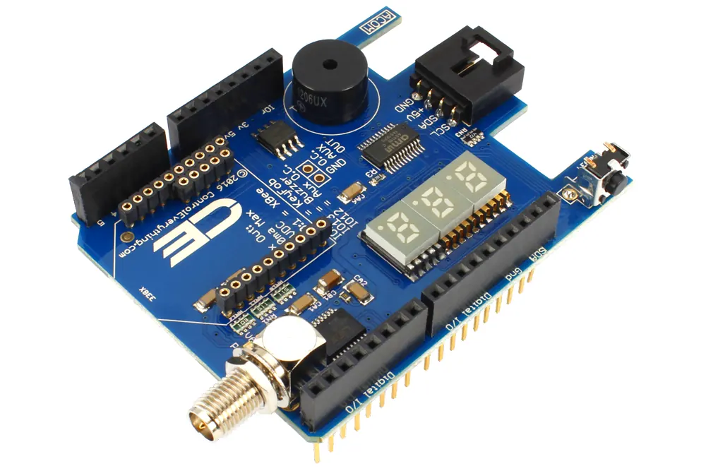
Using the notes provided above, program the passive buzzer to play the first line of "Twinkle Twinkle Little Star." The first line follows this pattern: C5, C5, G5, G5, A5, A5, G5 (each note having equal duration).
C4: 262 Hz | D4: 294 Hz | E4: 330 Hz | F4: 349 Hz | G4: 392 Hz | A4: 440 Hz | B4: 494 Hz |
C5: 523 Hz | D5: 587 Hz | E5: 659 Hz | F5: 698 Hz | G5: 784 Hz | A5: 880 Hz | B5: 988 Hz |
C6:1047 Hz|
Using the notes provided above, program the passive buzzer to play the first line of "Twinkle Twinkle Little Star." The first line follows this pattern: C5, C5, G5, G5, A5, A5, G5 (each note having equal duration).
 |
 |
 |
More fun code to try out:
Listen to the pitch as the frequency increases:
Frequency Sweep Buzzer
int buzzerPin = 8;

void setup() {
  Serial.begin(9600);
  pinMode(buzzerPin, OUTPUT);
  tone(buzzerPin, 1000, 2000);
}

void loop() {
  for (int i = 0; i <= 800; i = i +5){
    tone(buzzerPin, i, 500); // A4
    Serial.println(i);
    delay(200);
  }
  noTone(buzzerPin);
  delay(1000);
}
How about some proper music with duration control to celebrate?
Happy Birthday Melody
int buzzerPin = 8;

// Happy Birthday melody notes
int notes[] = {392, 392, 440, 392, 523, 494, 392, 392, 440, 392, 587, 523};
int durations[] = {500, 500, 1000, 1000, 1000, 2000, 500, 500, 1000, 1000, 1000, 2000};

void setup() {
  pinMode(buzzerPin, OUTPUT);

  // Play the melody
  for (int i = 0; i < 12; i++) {
    tone(buzzerPin, notes[i]);
    delay(durations[i]);
    noTone(buzzerPin);
    delay(100); // Short pause between notes
  }
}

void loop() {
  // Play once then stop
}