Part 1: Hardware
Introduction to Servo Motor
A servo motor is a type of motor that can rotate to a specific angular position and maintain that position. Unlike standard DC motors that spin continuously, servo motors are designed for controlled movement within a limited range, typically 0 to 180 degrees.
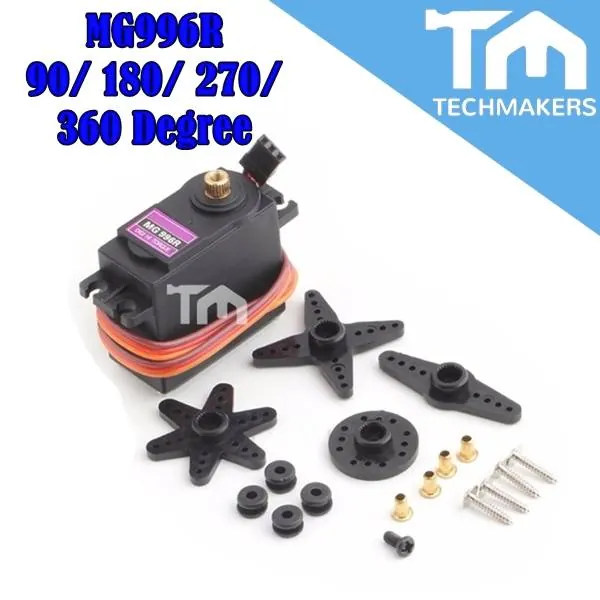
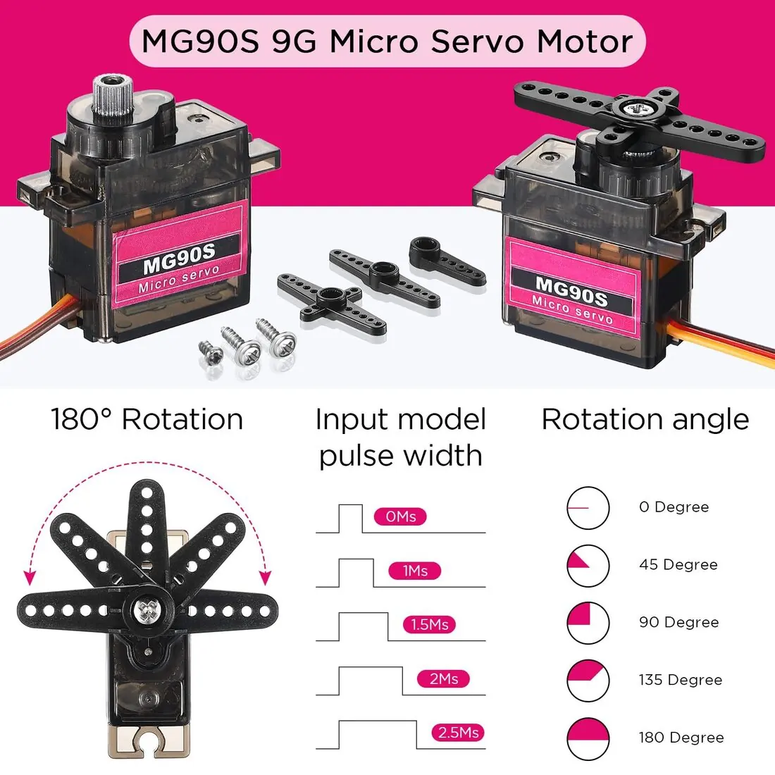
This makes them suitable for applications requiring precise angular control, such as steering mechanisms, robotic arms, and camera positioning systems. Many other versions are also commercially available.
This makes them suitable for applications requiring precise angular control, such as steering mechanisms, robotic arms, and camera positioning systems. Many other versions are also commercially available.
 |
 |
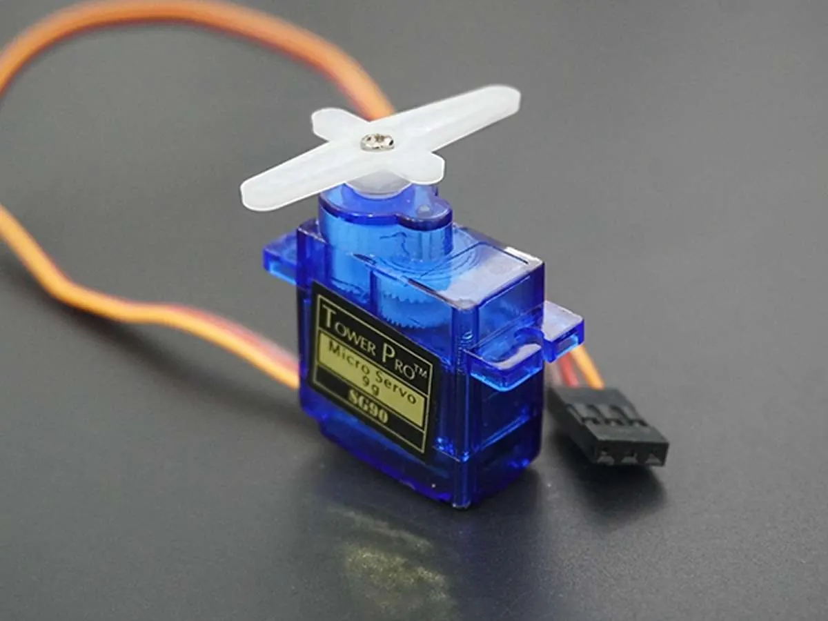 The common SG90 servo motor.
|
Physical Components and Operation
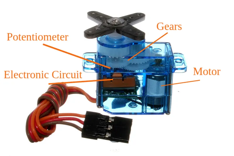
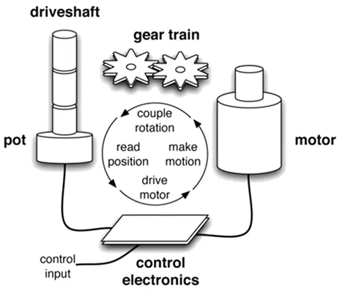
Servo motors contain a DC motor, a gear reduction system, a position sensor, and control circuitry. The position sensor, usually a potentiometer, continuously monitors the motor's current angle. The control circuitry compares this measured position with the desired position sent from the Arduino and adjusts the motor direction accordingly. This closed-loop system enables accurate position control.
 |
 |
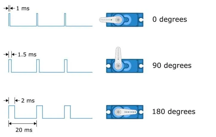
Servo motors are controlled using a specific type of Pulse Width Modulation (PWM) where the angle is determined by the duration of a electrical pulse sent every 20 milliseconds; a 1.5ms pulse centers the servo at 90 degrees, while pulses of 1.0ms and 2.0ms correspond to the 0 and 180 degree limits respectively. The Arduino's Servo library manages this precise timing by using the board's hardware timers to generate these accurate 50Hz signals, converting simple angle commands from the user into the correct pulse widths for positional control.
Electrical Connection
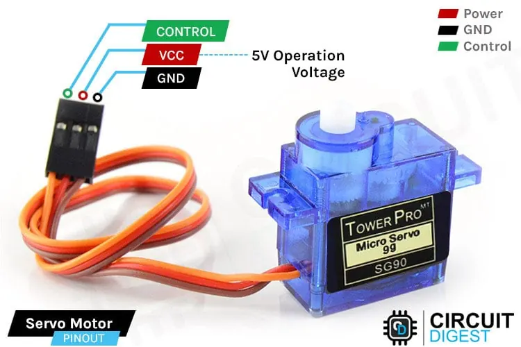
Standard servo motors have three wires: power, ground, and signal. The power wire (typically red) connects to 5V on the Arduino, while the ground wire (black or brown) connects to GND. The signal wire (yellow, orange, or white) connects to a digital pin. For larger servos, an external power supply may be necessary to prevent overloading the Arduino's voltage regulator.
Part 2: Software
The Servo Library
The Arduino IDE includes a Servo library that simplifies motor control. This library handles the pulse width modulation signals required to command servo positions. To use the library, you must include it at the beginning of your sketch with #include <Servo.h>. This provides access to functions that manage servo movement without requiring low-level signal timing calculations.
Servo Library Include
#include <Servo.h>
Basic Position Control
After creating a Servo object with Servo myServo and attaching it to a pin using servo.attach(pin), you can set the motor position with servo.write(angle). The angle parameter is an integer value between 0 and 180 degrees. The servo will rotate to the specified position and hold it until given a new command. The motor's internal feedback mechanism maintains the position against external forces.
Servo Object and Methods
Servo myServo;
servo.attach(pin);
servo.write(angle);
Programming Movement Sequences
By combining the write() function with delay() commands, you can create controlled movement patterns. For smooth motion between positions, you can use for loops to increment the angle gradually. This approach prevents abrupt movements and allows for precise control over the speed and path of the servo's rotation.
Exercise 1: Servo Sweep
|
Examine the following code that moves the servo motor from 90 degrees to 180 degrees, then return to 90 degrees.
Challenge:
|
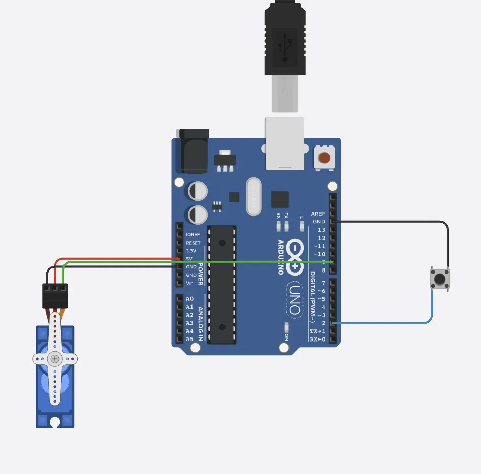 Click image for simulation
|
Basic Servo Control
#include <Servo.h>

Servo myServo;

void setup() {
  myServo.attach(9);  // Servo connected to digital pin 9
}

void loop() {
  myServo.write(90);
  delay(2000);

  myServo.write(180);
  delay(2000);  // Wait for 2000ms
}
Exercise 2: Sweep Speed
Move the servo between two positions with control speeds using delay.
Challenge:
Challenge:
- Slow down the rotational speed.
Servo Sweep Motion
#include <Servo.h>

Servo myServo;
const int servoPin = 9;

void setup() {
  myServo.attach(servoPin);
}

void loop() {
  // sweep from 0 to 180
  for (int angle = 0; angle <= 180; angle += 2) {
    myServo.write(angle);
    delay(15); // smaller delay = faster sweep
  }
  // sweep back from 180 to 0
  for (int angle = 180; angle >= 0; angle -= 2) {
    myServo.write(angle);
    delay(15);
  }
}
Exercise 3: Two-Button Servo Controller
Use AI to help you finish the following task:
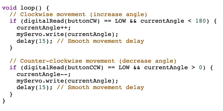
Create a system that allows precise control of a servo motor's position using two push buttons. One button will rotate the servo clockwise, while the other will rotate it counter-clockwise. The servo should move smoothly while a button is held down and stop when released, staying within its safe operating range of 0-180 degrees. One button is completed for you.
Create a system that allows precise control of a servo motor's position using two push buttons. One button will rotate the servo clockwise, while the other will rotate it counter-clockwise. The servo should move smoothly while a button is held down and stop when released, staying within its safe operating range of 0-180 degrees. One button is completed for you.
Servo Control with Pull-up Resistor
#include <Servo.h>

Servo myServo;
int buttonCW = 2;    // Clockwise button
int currentAngle = 90;

void setup() {
  myServo.attach(9);
  pinMode(buttonCW, INPUT_PULLUP);  // Enable internal pull-up resistor
  myServo.write(currentAngle);
}

void loop() {
  // Note: Button reads LOW when pressed (due to pull-up)
  if (digitalRead(buttonCW) == LOW && currentAngle < 180) {
    currentAngle++;
    myServo.write(currentAngle);
    delay(15);
  }
}
Hint