Part 1: Hardware
Introduction to Motion DetectionMotion detection is a common feature in modern technology, from automatic lighting to security systems. One of the key components that makes this possible is the Passive Infrared (PIR) sensor. This chapter introduces how PIR sensors work, how to connect them to an Arduino, and how to use them to trigger simple actions based on detected movement.
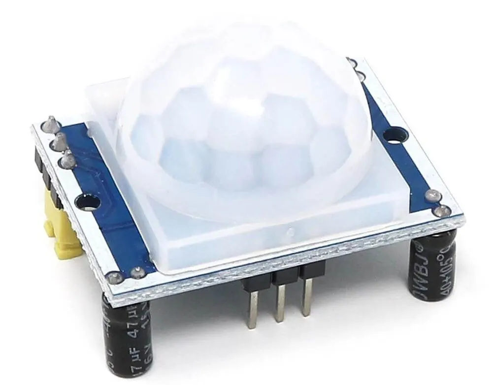
A Passive Infrared (PIR) sensor is an electronic device designed to detect changes in infrared radiation within its field of view. Unlike active sensors that emit energy, a PIR sensor is "passive," meaning it only receives infrared radiation emitted or reflected by objects in the environment. All objects with a temperature above absolute zero emit some level of infrared radiation. Warm-blooded animals, including humans, emit infrared radiation that peaks within a specific wavelength range. The PIR sensor is particularly sensitive to this range, making it effective for detecting human and animal movement. |
  |
How Does a PIR Sensor Detect Motion?
|
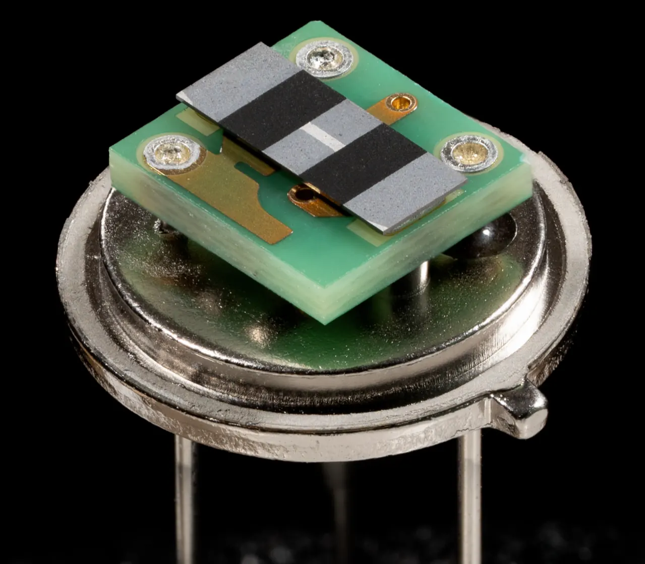
The core of a typical PIR sensor is a pyroelectric sensing element. This material generates a small electrical voltage when exposed to infrared radiation.
To specifically detect movement rather than just the presence of a warm object, the sensor window is divided into two slots or elements. These two elements are connected so that they cancel each other out when they detect an equal amount of infrared radiation. This means that a stationary, warm background does not trigger the sensor. |
 |
When a warm object, like a person, moves across the sensor's field of view, it first passes in front of one element and then the other. This sequential exposure causes a small, alternating electrical signal—a positive change followed by a negative change—to be generated. This signal indicates motion. The raw signal from the pyroelectric element is very weak, so it is immediately buffered and amplified by a built-in transistor within the sensor module.
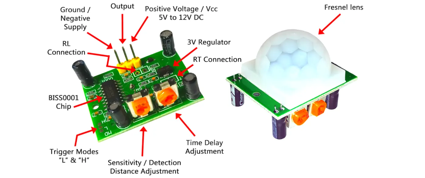
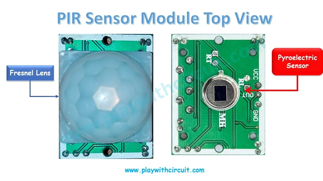
The small, rectangular PIR modules commonly used with Arduino and other microcontrollers do more than just house the basic sensor. They contain additional circuitry to make the sensor easier to use. This circuitry typically includes an operational amplifier (op-amp) chip, such as an LM324, which filters and further amplifies the tiny signal from the PIR element. This processing helps to reject false triggers from background noise and electrical interference.
Many modules also feature adjustable settings via small potentiometers. You can often adjust:
The module simplifies the complex analog signal processing into a simple digital output. When no motion is detected, the output pin is LOW (0V). When motion is detected, the output pin switches to HIGH (e.g., 3.3V or 5V) for the duration of the set time delay.
Many modules also feature adjustable settings via small potentiometers. You can often adjust:
- Sensitivity: This changes how much movement is required to trigger the sensor, allowing you to ignore small animals, for example.
- Time Delay: This sets how long the output signal remains high after motion is detected, controlling how long a connected light or alarm stays active.
The module simplifies the complex analog signal processing into a simple digital output. When no motion is detected, the output pin is LOW (0V). When motion is detected, the output pin switches to HIGH (e.g., 3.3V or 5V) for the duration of the set time delay.
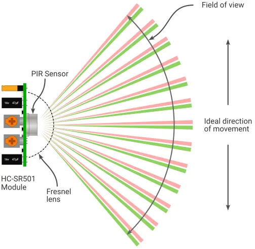
To increase the sensor's effective range and field of view, a Fresnel lens is often placed in front of it. This lens is made of multiple facets that focus infrared radiation from different zones onto the sensing element, creating a wider detection area and making the sensor more sensitive to smaller movements.
Connecting a PIR Sensor to Arduino
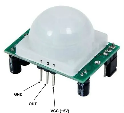 |
Connecting a standard three-pin PIR sensor module to an Arduino is straightforward, as it requires only power, ground, and a single signal wire.
Wiring:
|
Part 2: Software
PIR Motion Sensor with Edge Detection
int prevState = LOW;  // Store previous sensor state

void setup() {
  pinMode(2, INPUT);   // PIR sensor on pin 2
  Serial.begin(9600);  // Start serial
}

void loop() {
  int currentState = digitalRead(2);  // Read PIR

  if (currentState != prevState) {    // Only if state changed
    if (currentState == HIGH) {
      Serial.println("Motion Detected!");
    } else {
      Serial.println("Motion Stopped.");
    }
    prevState = currentState;  // Update previous state
  }
}
Exercise 1: The "Museum Guard" Security System
|
Objectives: Digital Input & Serial Output
Description: You are upgrading the museum security system. In addition to turning on the Alarm LED, the system must now send a text alert to the security guard's computer screen whenever movement is detected. Your Goal: Fill in the gaps (underscores) in the provided C++ sketch. Use the instructional comments to initialize the Serial Monitor and send the alert message. |
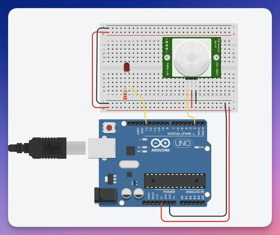 Click the image for the simulation
|
Museum Security System Template
// Project: Museum Security System (Upgraded)
// Context: Turn on LED and print "Intruder detected!" when motion is found.

int pirPin = _____;          // The pin the PIR sensor is connected to
int alarmLed = _______;       // The pin the LED is connected to
int sensorState = 0;     // Variable to store the sensor reading

void setup()
{
  pinMode(pirPin, _______); // define state for PIR sensor (INPUT/OUTPUT)
  pinMode(alarmLed, ________); // define state for LED (INPUT/OUTPUT)

  Serial.__________(9600);   // GAP: Initialize communication with the computer at 9600 bits per second
}

void loop()
{
  sensorState = digitalRead(__________);   // Read the current digital state of the PIR sensor

  if (sensorState == HIGH) {   // Check if the sensor state is HIGH (motion detected)

    digitalWrite(alarmLed, HIGH);

    // GAP: Print the warning message "Intruder detected!" to the Serial Monitor
    Serial.__________("Intruder detected!");     // (Hint: Use the command that prints a line of text)


  } else {

    digitalWrite(alarmLed, LOW);
  }

  delay(10);
}
Exercise 2: The "Siren & Strobe" Alarm
Objectives: Loops & Multiple Outputs
Description: A silent alarm isn't always enough! You need to upgrade the security system to trigger a loud noise and a flashing light to scare away the intruder.
Context: When the PIR sensor detects motion, the system should trigger an alarm sequence: the LED flashes and the Buzzer sounds 5 times in a rhythm.
Your Goal: Fill in the gaps (underscores) to configure the buzzer and control it simultaneously with the LED inside the for loop.
Description: A silent alarm isn't always enough! You need to upgrade the security system to trigger a loud noise and a flashing light to scare away the intruder.
Context: When the PIR sensor detects motion, the system should trigger an alarm sequence: the LED flashes and the Buzzer sounds 5 times in a rhythm.
Your Goal: Fill in the gaps (underscores) to configure the buzzer and control it simultaneously with the LED inside the for loop.
Siren & Strobe Security System Template
// Project: Siren & Strobe Security System
// Context: If motion is detected, flash LED and sound Buzzer 5 times.

int sensorPin = 2;
int ledPin = 13;
int buzzerPin = ______;  // The pin the Buzzer is connected to
int motionState = 0;

void setup()
{
  pinMode(sensorPin, INPUT);
  pinMode(ledPin, OUTPUT);

  pinMode(buzzerPin, __________);   // The buzzer produces sound, so it is an OUTPUT device

}

void loop()
{
  motionState = digitalRead(sensorPin);

  if (motionState == ________) { // should HIGH for there is any motion detected

    // Run this alarm loop 5 times
    // (i starts at 0, runs while i is less than 5)
    for (int i = 0; i < __________; i++) { // value should be equal to 5

      // Turn BOTH the Light and Sound ON
      digitalWrite(ledPin, HIGH);

      digitalWrite(buzzerPin, __________);       // Turn the buzzer on (HIGH)

      delay(200); // Alarm duration

      // Turn BOTH the Light and Sound OFF
      digitalWrite(ledPin, LOW);
      digitalWrite(buzzerPin, LOW);

      delay(200); // Silence duration
    }

    // Pause briefly after the alarm sequence finishes
    delay(1000);

  } else {
    // Ensure everything is off when no motion
    digitalWrite(ledPin, ______); //value is equal to be LOW
    digitalWrite(buzzerPin, _______); //value is equal to be LOW
  }
}