The RGB LED and Color Mixing
|
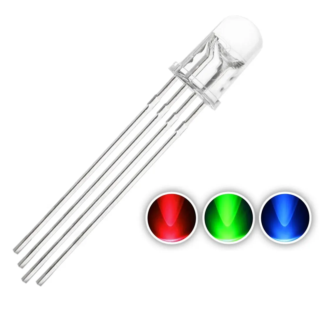
An RGB LED is a single component that contains three tiny light-emitting diodes within one housing: one red, one green, and one blue.
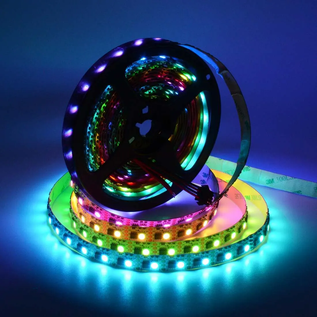
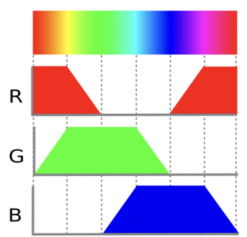
By controlling the individual brightness of each of these colored diodes, it is possible to create a wide variety of combined colors. This process is known as additive color mixing, where different amounts of red, green, and blue light are combined. For instance, mixing red and green light produces yellow, while combining all three colors at full brightness creates white light. |
 |
 |
 |
Common Cathode Configuration
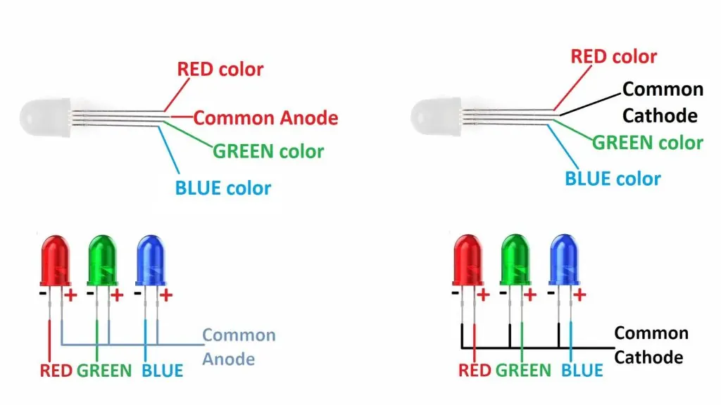
We will focus on common cathode configuration. This means the three internal LEDs share a single negative connection (cathode), while each has its own positive connection (anode) for its respective color.
- In a circuit, the common cathode pin is connected to the Arduino's ground (GND).
- The red, green, and blue anode pins are each connected to a separate digital pin on the Arduino through a current-limiting resistor.
AnalogWrite and Pulse Width Modulation
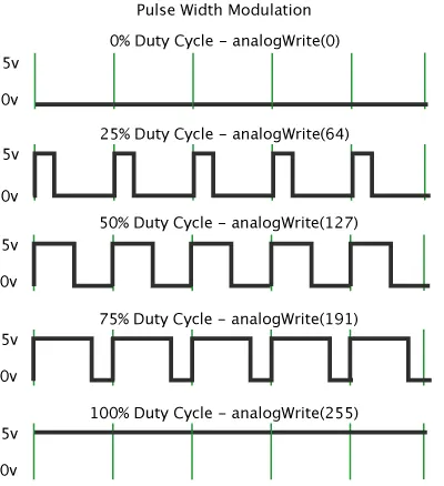
To create different colors, you need to control the brightness of each diode, not just turn them on or off. This is achieved using Pulse Width Modulation (PWM). PWM works by rapidly turning a digital pin on and off.
The ratio of the time the signal is on (high) versus off (low) within a cycle is called the duty cycle. A higher duty cycle results in a brighter light from the LED.
The ratio of the time the signal is on (high) versus off (low) within a cycle is called the duty cycle. A higher duty cycle results in a brighter light from the LED.
 |
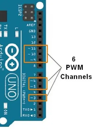 |
On the Arduino, only pins marked with a tilde (~) can generate a PWM signal. The analogWrite() function is used to set the duty cycle, with a value from 0 (fully off) to 255 (fully on).
AnalogWrite Syntax
analogWrite(redPin, 255);
analogWrite(greenPin, 127);
analogWrite(bluePin, 0);
Switch Case
The switch statement evaluates a single variable or expression once and compares it against multiple possible constant values. Each potential matching value is defined using a case label followed by a colon.
After each case block, a break statement is typically used to exit the switch structure. If break is omitted, the program will continue executing the code in the next case below, regardless of whether that case matches the variable's value. This behavior is called "fall-through."
After each case block, a break statement is typically used to exit the switch structure. If break is omitted, the program will continue executing the code in the next case below, regardless of whether that case matches the variable's value. This behavior is called "fall-through."
Switch Statement Syntax
switch(variable) {
  case value1:
    // code to execute
    break;
  case value2:
    // code to execute
    break;
  default:
    // code to execute
    break;
}
- The default case is optional and serves as a catch-all that executes when no other cases match the variable's value. While not required, including a default case can help handle unexpected values.
- The values used in case labels must be constants—they cannot be variables or expressions that change during program execution. Common data types used in switch statements include char, int, and byte.
Exercise 1: Debugging the Setup
|
Check your circuit connections and code to ensure the RGB LED works correctly.
|
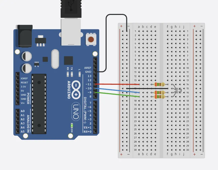 Click the image for the simulation
|
RGB LED with Pin Mode Issue
int redPin = 13;
int greenPin = 12;
int bluePin = 11;

void setup() {
  pinMode(redPin, INPUT);
  pinMode(greenPin, OUTPUT);
  pinMode(bluePin, OUTPUT);
  Serial.begin(9600);
}

void loop() {
  analogWrite(redPin, 255);
  analogWrite(greenPin, 128);
  analogWrite(bluePin, 0);
  delay(1000);
}
Exercise 2: Automatic Color Cycle
Modify the code below such that the RGB alternate the colors white, red, orange, yellow, green, cyan, blue, purple and dark each for 1 second.
RGB Color Sequence Template
int redPin = 11;
int greenPin = 9;
int bluePin = 10;

void setup() {
  pinMode(redPin, OUTPUT);
  pinMode(greenPin, OUTPUT);
  pinMode(bluePin, OUTPUT);
}

void loop() {
  // White
  analogWrite(redPin, 255);
  analogWrite(greenPin, 255);
  analogWrite(bluePin, 255);
  delay(1000);

  // Red
  analogWrite(redPin, 255);
  analogWrite(greenPin, 0);
  analogWrite(bluePin, 0);
  delay(1000);

  // Continue this pattern for orange, yellow, green, cyan, blue, purple, dark
  // Add the remaining colors following the same structure
}
Exercise 3: Complete Switch Case
Modify the following code such that it display the above colours when typed “w”, “r”, “o”, “y”, “g”, “c”, “b”, “p”, “d” in the serial monitor.
RGB Color Control
int redPin = 11;
int greenPin = 9;
int bluePin = 10;

void setup() {
  pinMode(redPin, OUTPUT);
  pinMode(greenPin, OUTPUT);
  pinMode(bluePin, OUTPUT);
  Serial.begin(9600);
  Serial.println("Enter color letter: w, r, o, y, g, c, b, p, d");
}

void loop() {
  if (Serial.available() > 0) {
    char color = Serial.read();

    switch(color) {
      case 'w': // White
        analogWrite(redPin, 255);
        analogWrite(greenPin, 255);
        analogWrite(bluePin, 255);
        Serial.println("White");
        break;

      case 'r': // Red
        analogWrite(redPin, 255);
        analogWrite(greenPin, 0);
        analogWrite(bluePin, 0);
        Serial.println("Red");
        break;

      default:
        Serial.println("Unknown color - try: w, r, o, y, g, c, b, p, d");
        break;
    }
  }
}
Fun code to experiment with: Fading effect
|
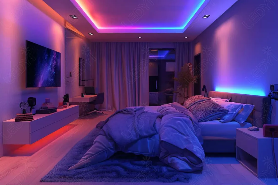
In practical applications, a fading effect provides a more smooth transition between colors, which is often preferred for creating ambient lighting or visual displays. While this code uses abrupt color changes, consider how you might modify it to create gradual color transitions.
|
 |
RGB LED Color Fading
// variables to hold the LED color
int rVal = 254;
int gVal = 1;
int bVal = 127;

int rDir = -1;
int gDir = 1;
int bDir = -1;

// constants to name the pins
const int rPin = 11;
const int gPin = 9;
const int bPin = 10;

void setup() {
  // declare the pinModes
  pinMode(rPin, OUTPUT);
  pinMode(gPin, OUTPUT);
  pinMode(bPin, OUTPUT);
}

void loop() {
  // PWM the LED
  // when using a common anode RGB LED like the ones in
  // your kits, you create a voltage difference across
  // each diode to light up the LED, that is, a PWM value
  // of 255 will turn that light off, while a PWM value of 0
  // will turn that light on fully.

  analogWrite(rPin, rVal);
  analogWrite(gPin, gVal);
  analogWrite(bPin, bVal);

  // change the values of the LEDs
  rVal = rVal + rDir;
  gVal = gVal + gDir;
  bVal = bVal + bDir;

  // for each color, change direction if
  // you reached 0 or 255
  if (rVal >= 255 || rVal <= 0) {
    rDir = rDir * -1;
  }

  if (gVal >= 255 || gVal <= 0) {
    gDir = gDir * -1;
  }

  if (bVal >= 255 || bVal <= 0) {
    bDir = bDir * -1;
  }

  // slight delay so it doesn't rotate color too quicky
  delay(10);
}