What is electricity?
To understand how electronic circuits function, we must become familiar with three fundamental concepts: voltage, current, and resistance.
- Voltage can be thought of as the electrical potential difference that pushes electrical charges through a circuit, measured in volts (V).
- Current refers to the flow of the electrical charges themselves, measured in amperes or amps (A).
- Resistance is a property that opposes or reduces the flow of current. Components designed to provide resistance are called resistors, and they are measured in ohms (Ω).
The Ohm's Law
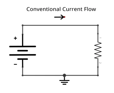
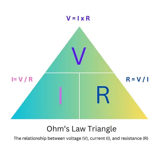
The relationship between voltage (V), current (I), and resistance (R) is described by Ohm's Law, expressed by the formula V = I × R.
|
The voltage across a component is equal to the current flowing through it multiplied by its resistance.
 |
 |
Identifying Resistor Values
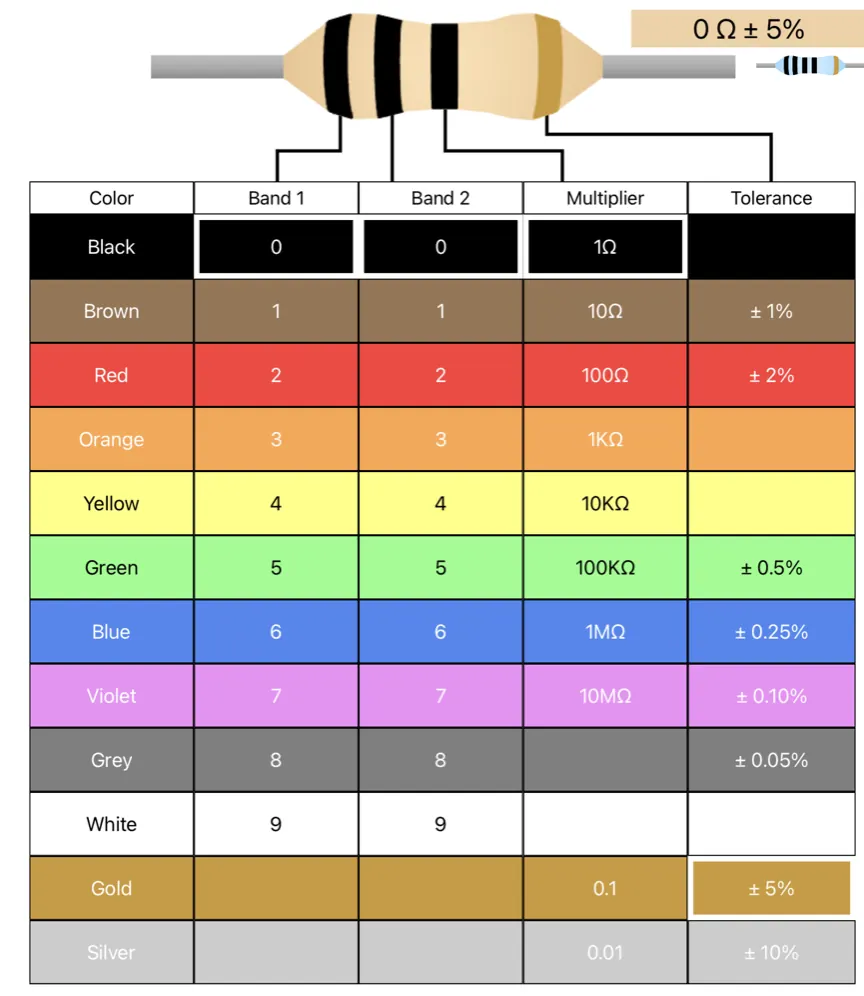
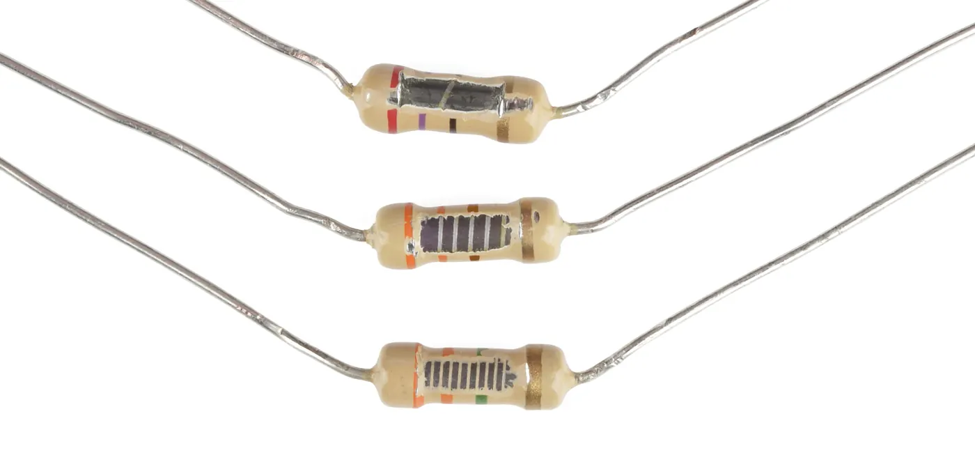
Many resistors use a color code system of painted bands to indicate their resistance value. Most resistors have four colored bands.
A chart matching colors to values is used to read these codes.
- The first two bands represent the first two digits of the resistance value.
- The third band is the multiplier, which indicates how many zeros to add to the first two digits.
- The fourth band indicates the tolerance, or the possible percentage variation from the stated value. For example, a resistor with bands colored brown (1), black (0), red (×100), and gold (±5%) has a value of 1000 ohms, or 1 kilo-ohm.
A chart matching colors to values is used to read these codes.
Factors that affect resistance
|
The resistance of a conductor is influenced by its physical properties.
|
 |
Resistors in Series and Parallel
|
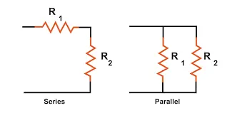
Resistors can be connected in different configurations that affect total resistance and current flow.
|
 |
The Voltage Divider Circuit
A voltage divider is a circuit configuration that uses two or more resistors connected in series to produce a specific, lower voltage from a higher input voltage. In this arrangement, the electrical current follows a single path through each resistor one after another.
When a voltage, such as 5V from an Arduino, is applied across the entire series of resistors, this represents the total electrical potential difference. As the current passes through the first resistor, some of this electrical potential is dropped, meaning the voltage decreases. The current then reaches a point between the resistors where the remaining voltage can be measured. As it continues through the next resistor, more voltage is dropped until it reaches zero potential, a point we call Ground.
When a voltage, such as 5V from an Arduino, is applied across the entire series of resistors, this represents the total electrical potential difference. As the current passes through the first resistor, some of this electrical potential is dropped, meaning the voltage decreases. The current then reaches a point between the resistors where the remaining voltage can be measured. As it continues through the next resistor, more voltage is dropped until it reaches zero potential, a point we call Ground.
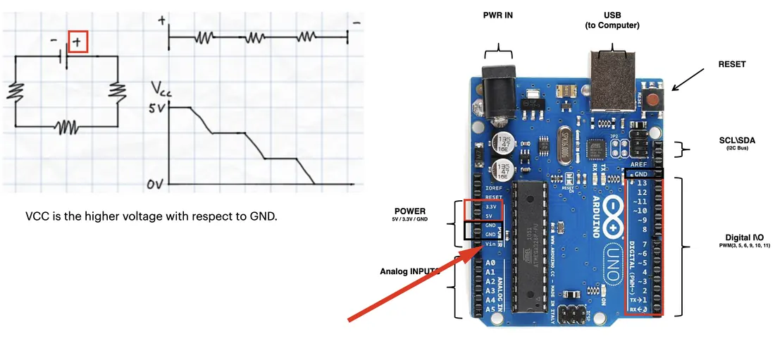
In electronic circuits, Ground (often abbreviated GND) serves as a common reference point for measuring voltage. It is not necessarily the same as the earth ground in a building's electrical system; in a simple circuit like this, it is the point defined to be at zero volts. All other voltages in the circuit are measured relative to this point. You can think of voltage as the height of a hill, with Ground being the bottom. A voltage divider creates a stable point partway down the hill.
Exercise:
|
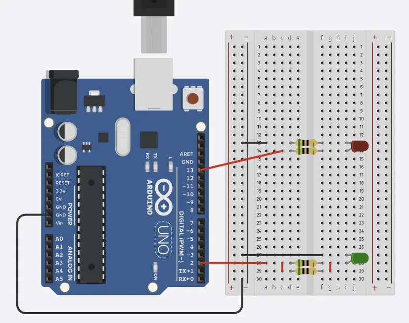
This exercise demonstrates how resistors behave differently in series versus parallel configurations with LEDs.
|
 |
Alternating LED Blink
int redLED = 13;
int greenLED = 2;

void setup() {
  pinMode(redLED, OUTPUT);
  pinMode(greenLED, OUTPUT);
}

void loop() {
  digitalWrite(redLED, HIGH);
  delay(1000);

  digitalWrite(redLED, LOW);
  delay(1000);

  digitalWrite(greenLED, HIGH);
  delay(1000);

  digitalWrite(greenLED, LOW);
  delay(1000);
}
Modification exercise:
- Rewrite the given code to make the red and green LEDs alternate their blinking pattern without using the delay() function. Instead, use millis() to track time and create non-blocking timing control.
- Add 3 more LEDs and modify your code to control five LEDs that turn on one at a time in sequence, then all turn off simultaneously before repeating.