Thrust: The Reaction Force
Before delving into the complex machinery, we must recall the fundamental physical principle that makes rocketry possible -- Newton's Third Law of Motion:
"For every action, there is a reaction force, equal in magnitude and opposite in direction."
|
In the context of a rocket, the "action" is the rapid expulsion of high-velocity mass (the exhaust gases) rearward. The "reaction" is the forward force exerted on the rocket engine, and by extension, the entire vehicle. This force is thrust. A rocket engine, therefore, is fundamentally a device designed to generate and accelerate a massive amount of gas as efficiently as possible. Its structure must be able to withstand immense heat, pressure, and vibration.
This chapter will investigate the structure of the Liquid Propellant Rocket Engine and the Solid Propellant Rocket Engine, and attempt to explain how is thrust force being generated by these engines. |
 |
Solid Rocket Engine Design
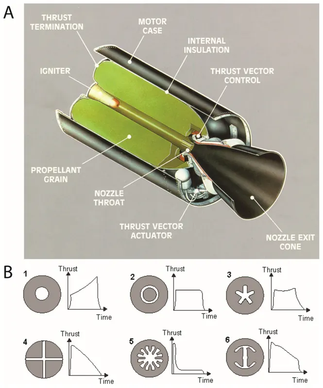 |
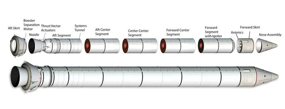
Solid rocket motors (SRMs) are mechanically simpler than liquid engines but cannot be throttled or shut down after ignition. Their design integrates the propellant storage and combustion chamber into a single unit, centered around a high-strength casing that contains the solid propellant grain.
This grain is a solid mixture of fuel and oxidizer bound in a polymer, and its pre-cast internal geometry dictates the motor's thrust profile over time. The system is protected by an insulation liner that shields the casing from extreme heat and a nozzle that manages thermal loads through ablative erosion. Ignition is achieved by a pyrotechnic igniter that ensures instantaneous, uniform combustion across the grain's surface. |
Liquid Rocket Engine Design
|
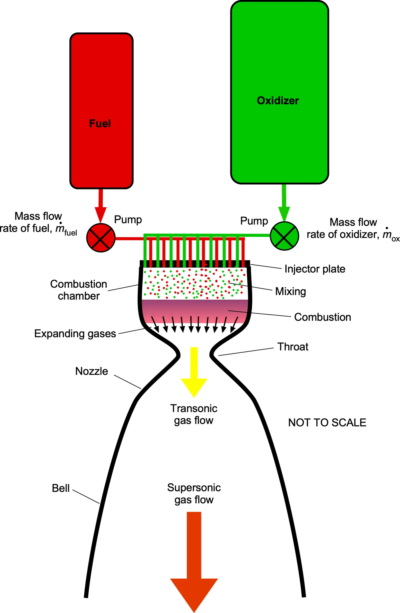
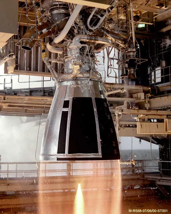
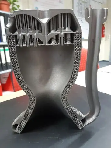
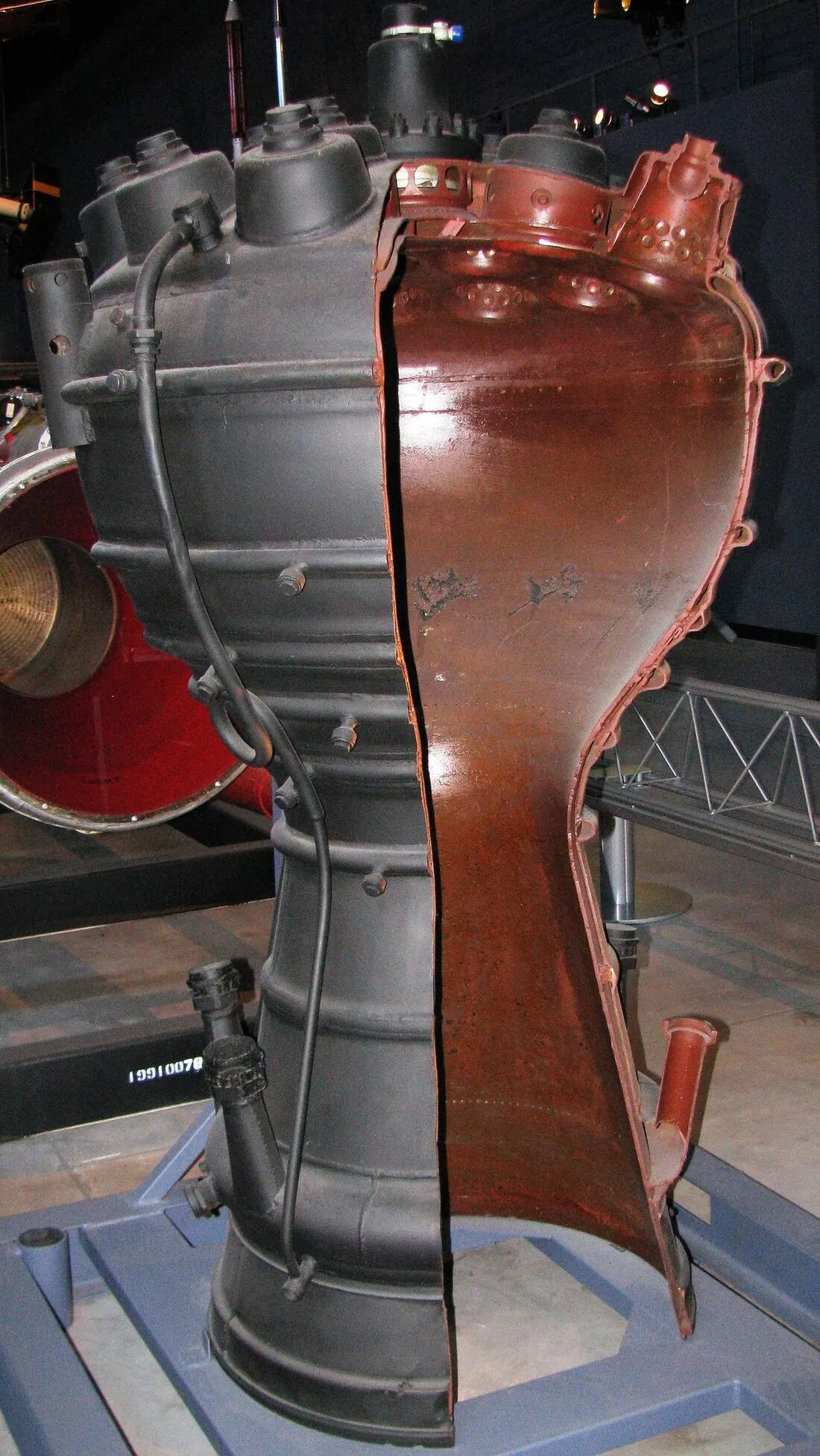
The combustion chamber is where propellants combust, converting chemical energy into thermal energy. Its construction is designed to contain this extreme high-pressure, high-temperature process. Typically cylindrical and converging, it is made from advanced superalloys like Inconel to withstand the severe environment. To prevent melting, regenerative cooling is often employed, where fuel is circulated through channels in the chamber walls before injection. This dual-purpose system cools the structure while pre-heating the propellant for improved efficiency.
 |
 |
 |
The fuel injector is a component at the head of the combustion chamber, tasked with atomizing, and mixing the liquid propellants.
It is typically a plate or manifold featuring an array of small orifices. Designs range from simple showerhead patterns to more efficient impinging jets, where fuel and oxidizer streams collide for fine atomization. |
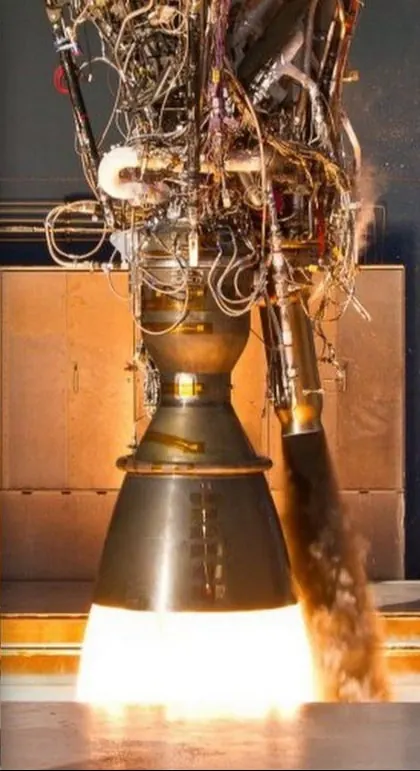
The nozzle is the primary component for generating thrust, converting the thermal energy of combustion into directed kinetic energy. Its function is to accelerate high-pressure gases to extreme velocities.
This is achieved through its de Laval shape:
This is achieved through its de Laval shape:
- A converging section compresses subsonic gases to sonic speed at the throat, after which a diverging section (bell) allows the supersonic gases to expand and accelerate further, producing a net forward force known as pressure thrust.
 |
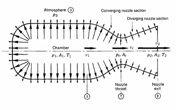 |
The generation of thrust is a story of pressure management. Inside the combustion chamber, pressure is immensely high, but gas velocity is subsonic. The nozzle's primary function is to transform this static, high-pressure energy into directed kinetic energy. It does this by guiding the gas through a constricting throat and then an expanding bell. This geometry forces the gas to accelerate to supersonic speeds, converting its high internal pressure into high velocity and, consequently, lowering its pressure significantly by the time it exits.

The high-velocity ejection of this mass generates the reactive thrust force, as defined by the thrust equation. The engine's physical construction directly determines some key variables: mass flow rate (ṁ), exhaust velocity (v_exhaust), exit pressure (P_exhaust), area of the exhaust nozzle (A_nozzle).
A lot of gas being exhausted at high speed generate high thrust.
A lot of internal-external pressure difference over some nozzle area generate high thrust.
For combustion rockets, we prefer to achieve an internal-external pressure equalization to optimize efficiency (for reasons we will discuss in later chapter), so the second term in the equation is cancelled.
Water rockets, on the other hand, would greatly rely on the pressure difference over the nozzle area. The pressure of the exiting fluid (P_exhaust) meets the ambient atmospheric pressure (P_atm). It is the imbalance between this internal gas pressure and the constant external atmospheric pressure, combined with the momentum of the high-velocity exhaust stream, that generates the net forward force we call thrust.
Water rockets, on the other hand, would greatly rely on the pressure difference over the nozzle area. The pressure of the exiting fluid (P_exhaust) meets the ambient atmospheric pressure (P_atm). It is the imbalance between this internal gas pressure and the constant external atmospheric pressure, combined with the momentum of the high-velocity exhaust stream, that generates the net forward force we call thrust.
Propellant Feed System
|
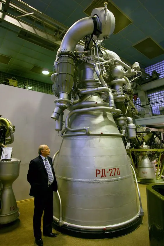
The propellant feed system delivers propellants from the tanks to the combustion chamber at the required flow rate and pressure, with two primary types representing a trade-off between simplicity and performance.
This can be a less efficient gas-generator cycle or a more efficient staged-combustion cycle that utilizes all propellant in the main chamber. |
 |
Summary
The process begins with propellant injection and mixing, followed by combustion that transforms chemical energy into high-pressure thermal energy. This gas is then accelerated through the nozzle's converging-diverging geometry, converting thermal energy into directed kinetic energy. The resulting high-velocity exhaust creates thrust, where the engine's physical design directly determines the mass flow rate, exhaust velocity, and pressure characteristics.