Part 1: Hardware
Introduction to the Potentiometer
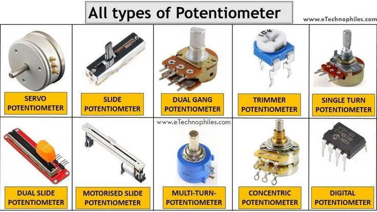
A potentiometer is a three-terminal component that provides a variable resistance. Often called a "pot," it typically has a knob or slider that, when turned or moved, changes the resistance between its center terminal and the two outer terminals. This adjustable resistance makes it useful for controlling electrical circuits manually. In many electronic devices, potentiometers are used as volume controls, brightness dials, or tuning knobs.
 |
 |
How a Potentiometer Works
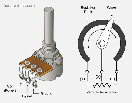
A potentiometer operates as an adjustable voltage divider by incorporating a variable resistor with three terminals. Inside its housing, a resistive track made of carbon, cermet, or conductive plastic extends between the two outer terminals. A movable contact called a wiper, connected to the center terminal, slides along this track when the knob is turned. As the wiper moves, it effectively divides the resistive element into two separate resistors in series, allowing the output voltage at the center terminal to be varied smoothly between the voltages applied to the outer terminals. This adjustable voltage output makes the potentiometer useful for controlling circuits manually.

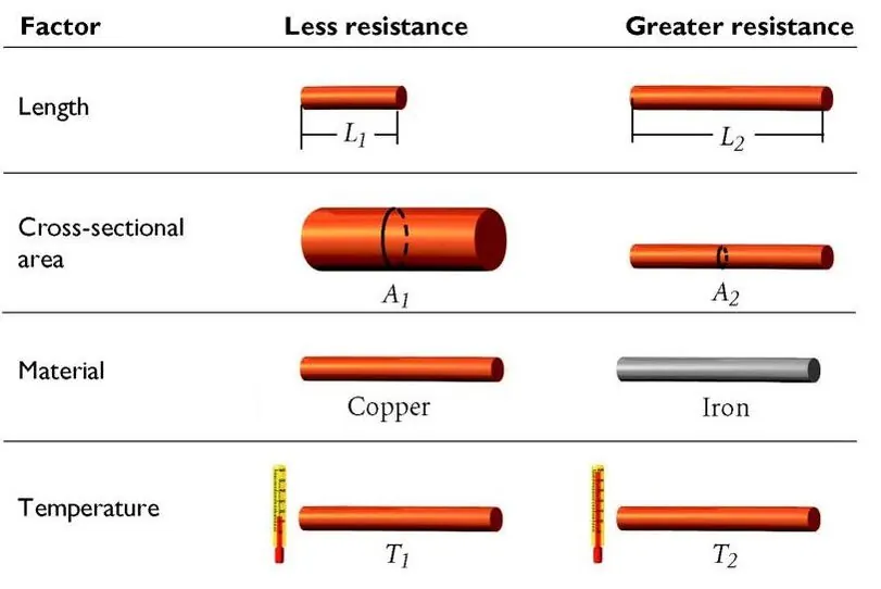
Potentiometers are inherently resistors, and therefore their behavior is governed by the same fundamental properties that affect all resistive components.
- The length of the conductor: a longer wire offers greater resistance than a shorter one of the same material and thickness.
- The cross-sectional area: as a thicker wire provides more pathways for current to flow, resulting in lower resistance.
- The material from which a conductor is made defines its inherent resistivity, explaining why copper is commonly used for wiring while other materials are chosen for specific applications.
- Finally, temperature: resistance typically increases as the conductor heats up due to increased atomic vibrations that impede electron flow.
Part 2: Software
Reading Potentiometer Inputs
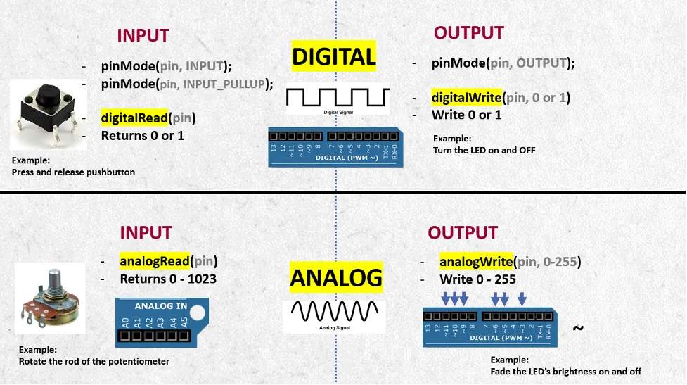
The Arduino can read the position of a potentiometer using its analog-to-digital converter (ADC). When connected with the outer terminals to 5V and GND, and the center terminal to an analog input pin, the potentiometer produces a voltage at the center terminal that varies from 0 to 5 volts. The Arduino's analogRead() function converts this voltage to a digital value between 0 and 1023, providing 1024 possible positions for the potentiometer knob.
analogRead Function Reference
analogRead(pin); //Syntax
analogRead(A0); //Example
Writing Analog Outputs
The analogWrite() function allows an Arduino to generate an output signal that is not simply on or off. Unlike digitalWrite(), which can only set a pin to its maximum voltage (5V) or zero volts, analogWrite() can produce a range of output levels. When using analogWrite(), you provide a value between 0 and 255.
The function works on specific digital pins marked with a tilde (~) on the Arduino board. These pins are capable of generating the variable output signals that analogWrite() produces. Before using the function, you must set the pin mode to OUTPUT using pinMode() in the setup section of your program. The output level set by analogWrite() will remain constant until the function is called again with a different value, allowing for stable control of connected devices.
- A value of 0 corresponds to an output of 0 volts, effectively turning the output off.
- A value of 255 corresponds to the maximum output voltage of 5 volts.
- Values between 0 and 255 produce intermediate output levels, with 127 representing approximately half the maximum voltage.
The function works on specific digital pins marked with a tilde (~) on the Arduino board. These pins are capable of generating the variable output signals that analogWrite() produces. Before using the function, you must set the pin mode to OUTPUT using pinMode() in the setup section of your program. The output level set by analogWrite() will remain constant until the function is called again with a different value, allowing for stable control of connected devices.
analogWrite() Reference
analogWrite(pin, value);  //Syntax
analogWrite(3, 255);  //Example
Integrated projects
Exercise 1: Controlling LED Brightness with a Potentiometer
|
In this exercise, you will learn how to use an analog input to control an analog output. A potentiometer will serve as your input device, acting as a variable voltage divider that the Arduino can read. The values from the potentiometer will then be used to control the brightness of an LED using pulse width modulation. This simulates how physical input devices can create smooth, continuous control over output components in an electronic circuit.
Challenge: Fix the code by performing minor changes
|
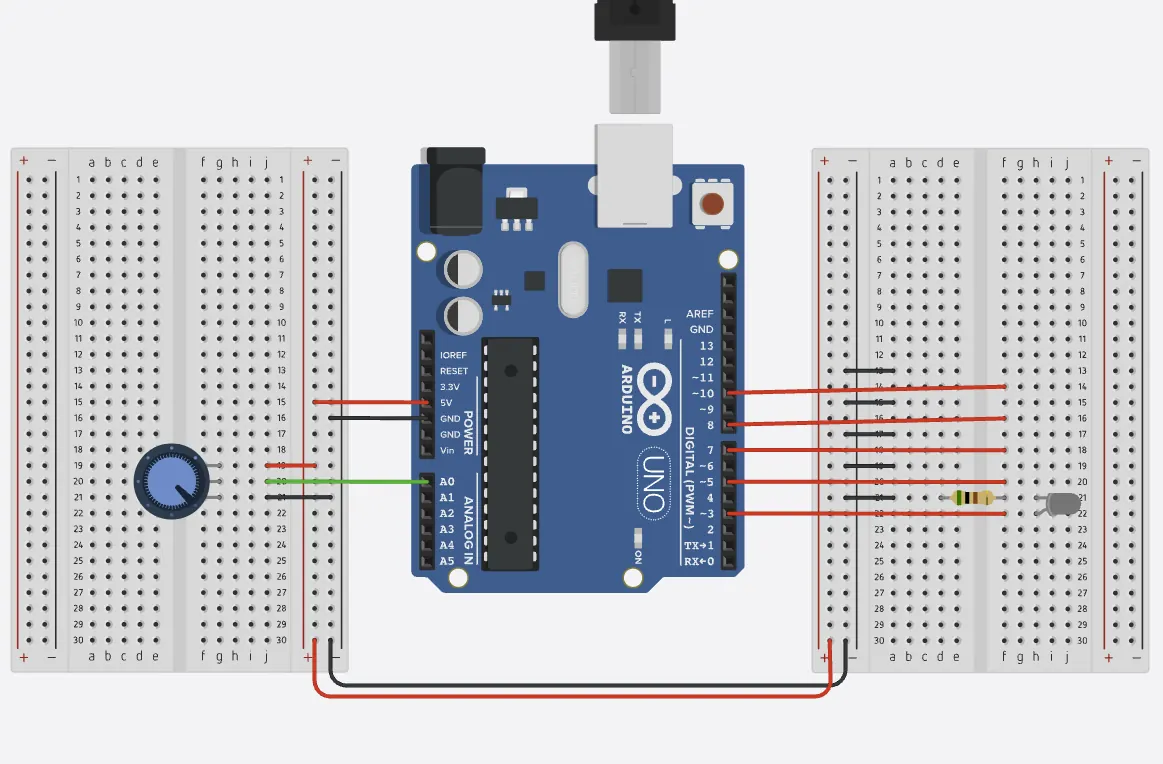 Click the image for interactive simulation.
|
LED Brightness Control Template
// PIN ASSIGNMENTS - FILL IN YOUR PIN NUMBERS:
const int potPin = ______;  // HINT: Analog pin for potentiometer (A0, A1, A2...)
const int ledPin = ______;  // HINT: Digital PWM pin for LED (~3, ~5, ~6, ~9, ~10, ~11)

void setup() {
  // Initialize the LED pin as an OUTPUT
  pinMode(______, OUTPUT);  // HINT: Use your ledPin variable here
}

void loop() {
  // Read the value from the potentiometer (0-1023)
  int potValue = analogRead(______);  // HINT: Use your potPin variable here

  // Convert the potentiometer value (0-1023) to PWM value (0-255)
  int brightness = map(potValue, 0, 1023, 0, 255);

  // Apply the brightness value to the LED using PWM
  analogWrite(______, ______);  // HINT: First blank = ledPin, second blank = brightness

  delay(10); // Small delay for stability
}
Exercise 2: LED Bar Graph
Your task is to wire up 5 LEDs and program them to create a bar graph display controlled by a potentiometer. When the potentiometer is at its minimum position, no LEDs should be lit. As you gradually turn the potentiometer, LEDs should light up one by one until all 5 are illuminated at the maximum position. You'll need to:
- Connect 5 LEDs to digital pins with appropriate resistors
- Read the potentiometer value using analogRead()
- Map the potentiometer reading (0-1023) to determine how many LEDs should be on (0-5)
- Write logic to control each LED based on the mapped value
- Test that the bar graph responds smoothly to potentiometer changes
LED Bar Graph (If Statement Template)
// PIN ASSIGNMENTS - FILL IN YOUR PIN NUMBERS:
const int potPin = ______;  // HINT: Analog pin for potentiometer
const int led1 = ______;    // HINT: Digital pin for LED 1
const int led2 = ______;    // HINT: Digital pin for LED 2
const int led3 = ______;    // HINT: Digital pin for LED 3
const int led4 = ______;    // HINT: Digital pin for LED 4
const int led5 = ______;    // HINT: Digital pin for LED 5

void setup() {
  pinMode(______, OUTPUT);  // HINT: Use led1 variable
  pinMode(______, OUTPUT);  // HINT: Use led2 variable
  pinMode(______, OUTPUT);  // HINT: Use led3 variable
  pinMode(______, OUTPUT);  // HINT: Use led4 variable
  pinMode(______, OUTPUT);  // HINT: Use led5 variable
}

void loop() {
  int potValue = analogRead(______);  // HINT: Use potPin variable
  int ledCount = map(potValue, 0, 1023, 0, 5);

  // Control each LED with clear if-else statements
  if (ledCount >= ___) {  // HINT: LED 1 turns on at level 1
    digitalWrite(led1, HIGH);
  } else {
    digitalWrite(led1, LOW);
  }

  if (ledCount >= ___) {  // HINT: LED 2 turns on at level 2
    digitalWrite(led2, HIGH);
  } else {
    digitalWrite(led2, LOW);
  }

  if (ledCount >= ___) {  // HINT: LED 3 turns on at level 3
    digitalWrite(led3, HIGH);
  } else {
    digitalWrite(led3, LOW);
  }

  if (ledCount >= ___) {  // HINT: LED 4 turns on at level 4
    digitalWrite(led4, HIGH);
  } else {
    digitalWrite(led4, LOW);
  }

  if (ledCount >= ___) {  // HINT: LED 5 turns on at level 5
    digitalWrite(led5, HIGH);
  } else {
    digitalWrite(led5, LOW);
  }

  delay(50);
}