Part 1: Hardware
Understanding Analog and Digital Signals
Electronic components communicate using two primary types of signals: digital and analog. A digital signal has only two possible values, typically represented as HIGH (on) or LOW (off). An analog signal, however, can vary continuously across a range of values. Think of a light switch versus a dimmer; the switch is digital (on/off), while the dimmer is analog, allowing for varying levels of brightness. Many sensors in the real world, such as those measuring light, sound, or temperature, provide analog information.
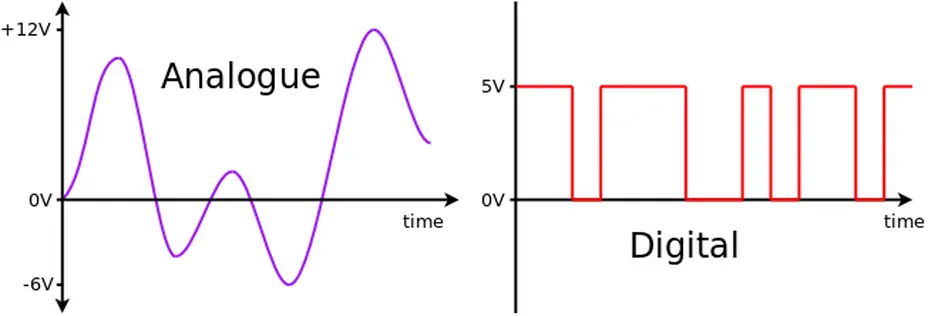
Digital signals have only two discrete states (HIGH/LOW), while analog signals can represent a continuous range of values.
|
Analog Devices Examples:
|
Digital Sensors Examples:
Digital Output Examples:
|
The Light Dependent Resistor (LDR)
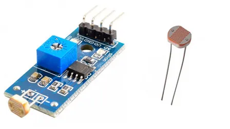
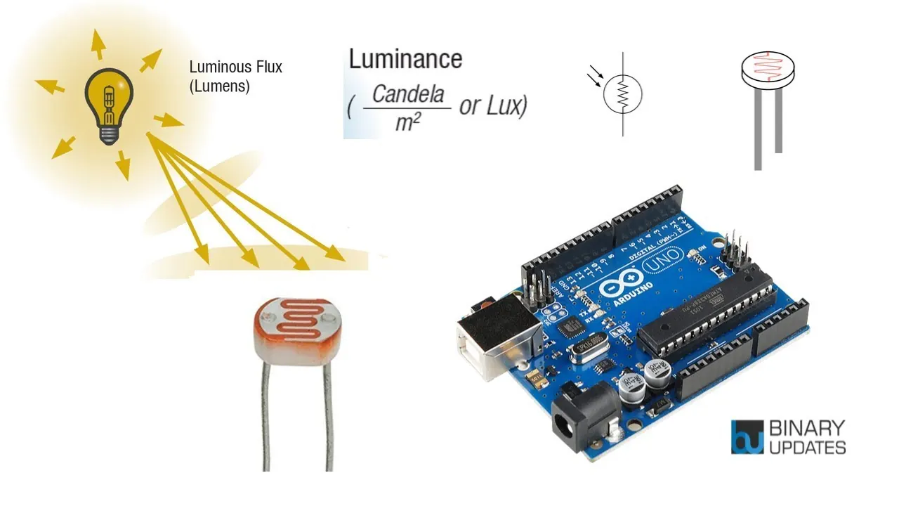
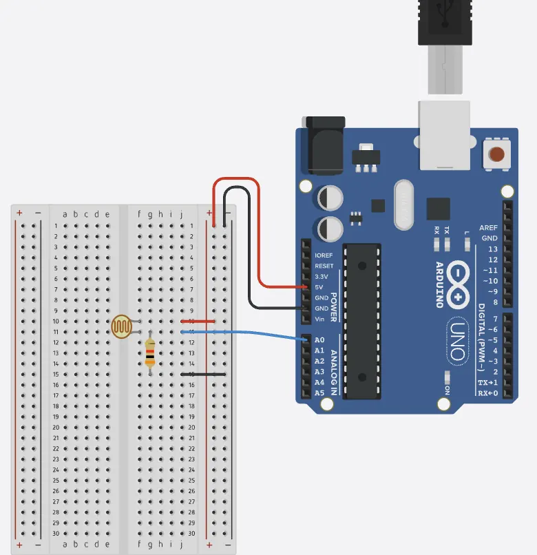
A Light Dependent Resistor (LDR) is a component that changes its electrical resistance based on the amount of light that falls upon it. In bright light, its resistance decreases, allowing more current to flow. In darkness, its resistance increases, restricting current flow. By connecting an LDR in a voltage divider circuit with a fixed resistor, we can convert this changing resistance into a varying voltage that an Arduino can measure.
 |
 |
Part 2: Software
Reading Analog Values with analogRead()
The Arduino uses a built-in Analog-to-Digital Converter (ADC) to read analog voltages. The analogRead() function is used for this purpose. When you call analogRead(A0) on a pin labeled A0, the Arduino returns an integer value between 0 and 1023. This number represents the voltage on the pin, where 0 corresponds to 0 volts and 1023 corresponds to 5 volts. This gives us a way to measure a continuous physical quantity, like light intensity, with our microcontroller.
analogRead Function Reference
analogRead(pin); //Syntax
analogRead(A0); //Example

Converting Sensor Values with the map() Function
|
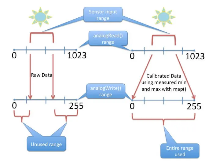
The raw values from analogRead() (0-1023) are not always directly useful. For instance, you might want to convert a light reading into a percentage or a value suitable for controlling another component. The map() function performs this conversion. It takes a value from one range and proportionally translates it to another range. The syntax is map(value, fromLow, fromHigh, toLow, toHigh). For example, you could map a sensor reading from its native range (0-1023) to a percentage range (0-100).
|
 |
map Function Reference
map(value, fromLow, fromHigh, toLow, toHigh); //Syntax
map(sensorValue, 0, 1023, 0, 100); //Example
Observing Data with the Serial Monitor
|
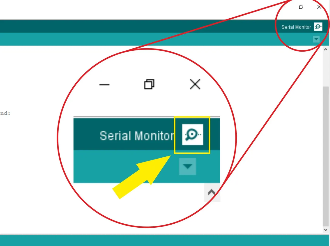
To see the values being read by your Arduino, you can use the Serial Monitor, a tool within the Arduino IDE. Communication with the Serial Monitor is started in the setup() function using Serial.begin(9600), which sets the data transmission rate. You can then use Serial.println() in your loop() to send readings to the computer. This allows you to observe how the LDR's value changes in response to light, which is helpful for testing and calibrating your circuit.
|
 |
Serial Communication Functions
Serial.begin(speed); //Syntax
Serial.println(data); //Syntax

Serial.begin(9600); //Example
Serial.println(sensorValue); //Example
Integrated projects
Ambient Light Level Monitor
|
This project creates a simple light measurement system using an Arduino and a Light Dependent Resistor (LDR). The LDR is a component that changes its electrical resistance based on the amount of light it detects. In bright conditions, its resistance decreases, while in darkness, its resistance increases.
The system works by reading the voltage across the LDR using the Arduino's analog-to-digital converter. The Arduino converts this voltage reading into a digital value between 0 and 1023. This raw value is then transformed into a more intuitive percentage scale (0-100%) that represents the relative light intensity in the environment. |
 Click the image for interactive simulation.
|
LDR Light Sensor Reader
int ldrPin = A0;
int rawValue;
int percentage;

void setup() {
  Serial.begin(9600);
}

void loop() {
  rawValue = analogRead(ldrPin);
  percentage = map(rawValue, 0, 1023, 0, 100);

  Serial.print("Raw: ");
  Serial.print(rawValue);
  Serial.print(" - Light Level: ");
  Serial.print(percentage);
  Serial.print("%");

  delay(1000);
}
Exercise 1:
Line-by-Line Output: Modify the code to display the raw value and percentage line-by-line using Serial.println(), instead of side-by-side, so that the displayed message become more readable.
Exercise 2:
Formatted Text Output: Change the output to read "The current light level is: X%" where X is the calculated percentage value.
Exercise 3:
|
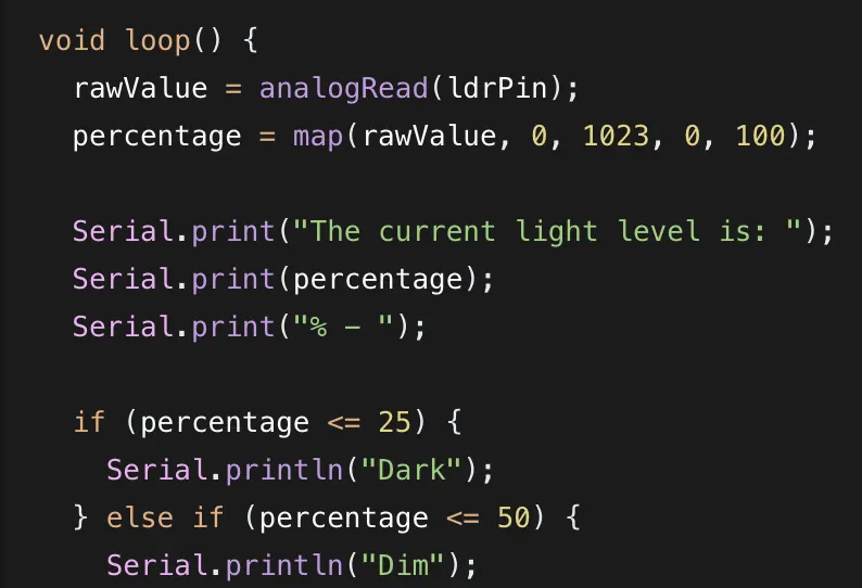
Modify the provided code so that it not only prints the light percentage but also a descriptive text message (e.g., "Dark", "Dim", "Bright", "Very Bright") based on the calculated percentage.
Copy and paste the entire text block below into your AI assistant if needed. |
 Hint:
|
Exercise 3 AI prompt (If Statement Template)
Please modify the following Arduino code. I want to add descriptive text to the serial output based on the light percentage.

The new rules are:
- If the percentage is 25% or less, print "Dark".
- If the percentage is between 26% and 50%, print "Dim".
- If the percentage is between 51% and 75%, print "Bright".
- If the percentage is above 75%, print "Very Bright".

Change the `Serial.print` statements to output in this new format: "The current light level is: [percentage]% - [descriptive_text]"

Here is the original code to modify:

"int ldrPin = A0;
int rawValue;
int percentage;

void setup() {
  Serial.begin(9600);
}

void loop() {
  rawValue = analogRead(ldrPin);
  percentage = map(rawValue, 0, 1023, 0, 100);

  Serial.print("Raw: ");
  Serial.print(rawValue);
  Serial.print(" - Light Level: ");
  Serial.print(percentage);
  Serial.print("%");

  delay(1000);
}"
Exercise 4:
|
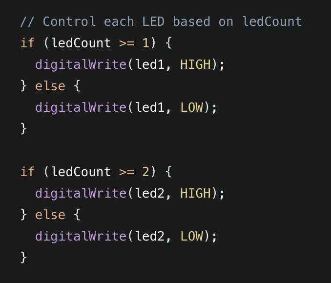
Progressive LED Light Indicator: Create a system where the number of lit LEDs indicates the ambient light level. In darkness, all 5 LEDs should be on. As light increases, fewer LEDs should be on, with only 1 LED remaining in bright conditions. Use AI for assistance if needed.
|
 Hint:
|
Exercise 4 AI prompt
Please modify and expand the following Arduino code to control 5 LEDs connected to digital pins 2, 3, 4, 5, and 6.

The behavior should be as follows:
- The `rawValue` from the LDR (which is between 0 and 1023) should be mapped to a `ledCount` variable. However, this time, map it so that a `rawValue` of 0 (dark) results in 5 LEDs on, and a `rawValue` of 1023 (bright) results in only 1 LED on. (Hint: use `map(rawValue, 0, 1023, 5, 1)`)
- Use a series of `if`/`else` statements to control each LED individually. For example, if `ledCount` is 3, then LEDs on pins 2, 3, and 4 should be turned ON (HIGH), and LEDs on pins 5 and 6 should be OFF (LOW).
- Add a print statement to the Serial Monitor that shows how many LEDs are currently lit.

Please remember to set the pin modes for all LEDs to OUTPUT in the `setup()` function.

Here is the original code to modify and expand:

"int ldrPin = A0;
int rawValue;
int percentage;

void setup() {
  Serial.begin(9600);
}

void loop() {
  rawValue = analogRead(ldrPin);
  percentage = map(rawValue, 0, 1023, 0, 100);

  Serial.print("Raw: ");
  Serial.print(rawValue);
  Serial.print(" - Light Level: ");
  Serial.print(percentage);
  Serial.print("%");

  delay(1000);
}"