Arduino
Arduino is a platform for building digital devices that can sense and control objects in the physical world. It originated in Italy at the Interaction Design Institute Ivrea in the early 2000s. The goal of the project was to create an accessible and low-cost tool for students and designers to build interactive prototypes without an extensive background in electronics. The project's open-source nature, meaning its designs and software are freely available, contributed to its widespread adoption.
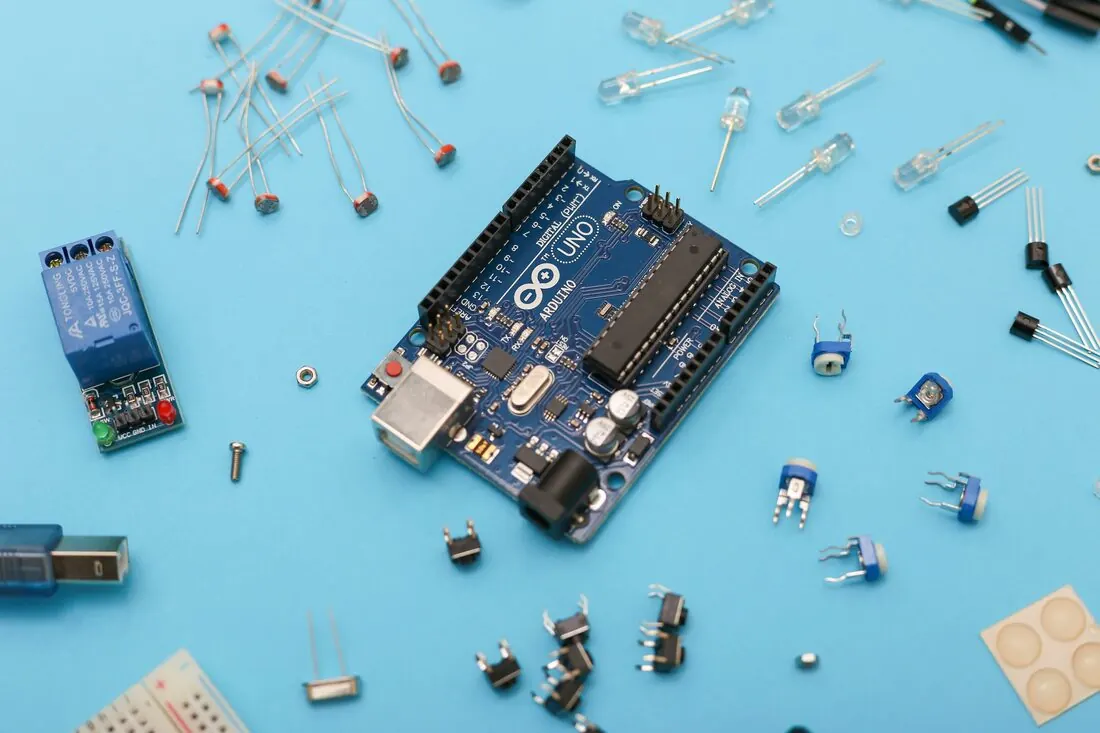
The most common board for beginners is the Arduino Uno. This board is a microcontroller, a small computer on a single integrated circuit. It can be powered via a USB connection from a computer or with an external power supply, such as a 9-volt battery. The board exposes a set of metal pins that allow you to connect wires and components. These pins have specific functions:
The most common board for beginners is the Arduino Uno. This board is a microcontroller, a small computer on a single integrated circuit. It can be powered via a USB connection from a computer or with an external power supply, such as a 9-volt battery. The board exposes a set of metal pins that allow you to connect wires and components. These pins have specific functions:
Arduino Pinout Diagram
Digital Pins (D0-D13): These pins can be configured as either inputs (to read a signal from a component like a button) or outputs (to send a signal to a component like an LED). A subset of these pins (marked with a ~ symbol, such as 3, 5, 6, 9, 10, and 11) can generate PWM (Pulse Width Modulation). PWM is a technique that mimics an analog output by rapidly turning a digital pin on and off. It is commonly used to control the brightness of LEDs or the speed of motors.
Analog Pins (A0-A5): These pins are dedicated to reading inputs from components that provide a range of values, like a potentiometer (dial).
Power Pins (5V, 3.3V, GND): These pins provide electrical power to the components you connect.
Analog Pins (A0-A5): These pins are dedicated to reading inputs from components that provide a range of values, like a potentiometer (dial).
Power Pins (5V, 3.3V, GND): These pins provide electrical power to the components you connect.
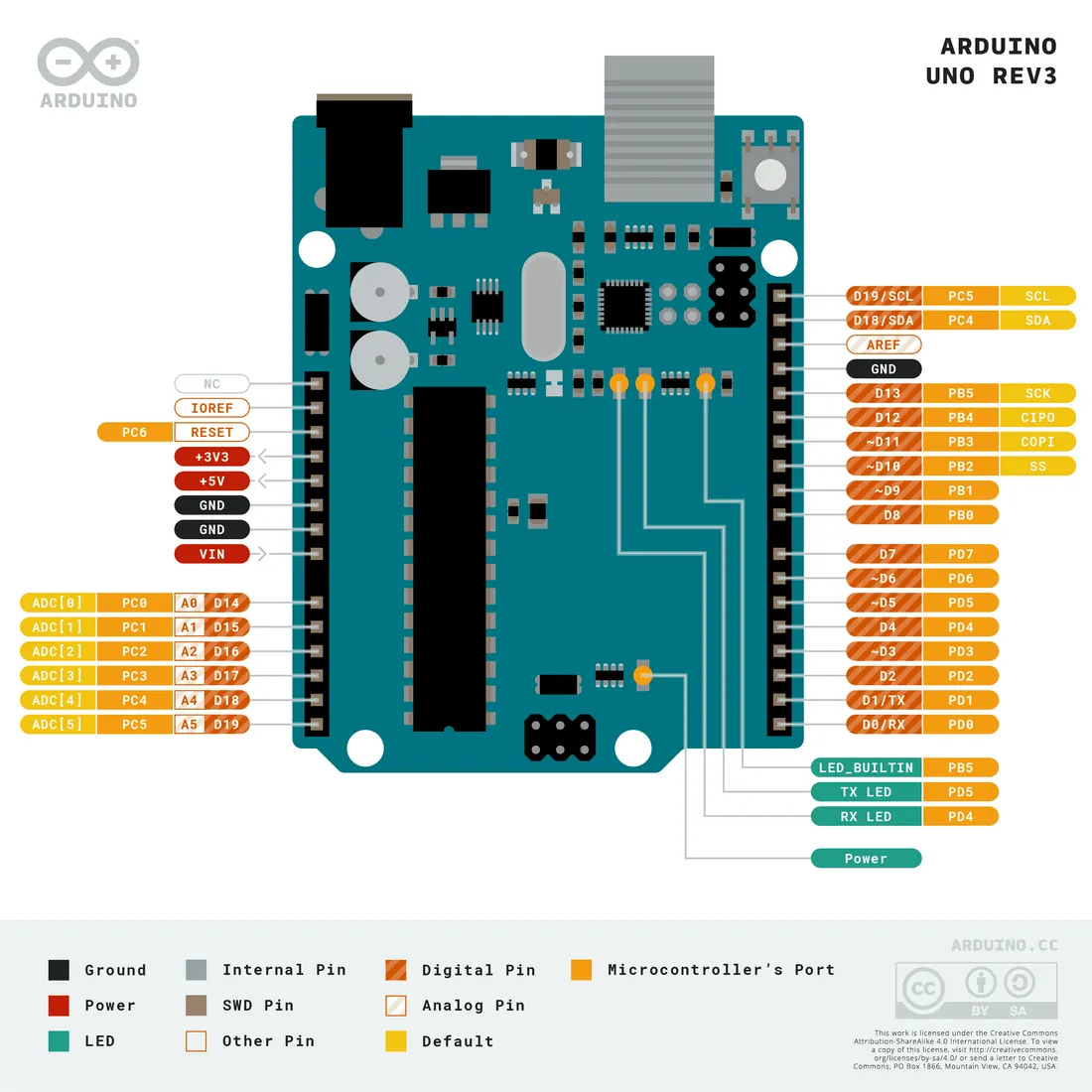
For your reference, you may also notice other labels on the board, many of which are related to more advanced communication protocols or internal functions:
Serial Communication: Pins 0 and 1 are labeled RX (receive) and TX (transmit). They are used for serial communication with a computer, which is how your sketch is uploaded and how the Serial Monitor sends and receives data.
SPI (Serial Peripheral Interface): This is a protocol for communicating with multiple devices. The pins involved are:
I²C (Inter-Integrated Circuit): This is another communication protocol that allows multiple devices to share the same two wires:
Other Labels:
Serial Communication: Pins 0 and 1 are labeled RX (receive) and TX (transmit). They are used for serial communication with a computer, which is how your sketch is uploaded and how the Serial Monitor sends and receives data.
SPI (Serial Peripheral Interface): This is a protocol for communicating with multiple devices. The pins involved are:
- CIPO (Controller In, Peripheral Out) or MISO: Data line from the peripheral to the controller.
- COPI (Controller Out, Peripheral In) or MOSI: Data line from the controller to the peripheral.
- SCK (Serial Clock): The clock signal that synchronizes data transfer.
- SS (Slave Select): Used to select a specific peripheral device.
I²C (Inter-Integrated Circuit): This is another communication protocol that allows multiple devices to share the same two wires:
- SDA (Serial Data): The line for data.
- SCL (Serial Clock): The line for the clock signal.
Other Labels:
- RESET: Connecting this pin to GND will restart the Arduino.
- IOREF (I/O Reference): This pin provides the voltage reference that the microcontroller operates on (5V for Uno), which allows shields (add-on boards) to adapt to the correct voltage.
- NC: This stands for "Not Connected" and indicates a pin that is not electrically connected to anything inside the chip.
- PB, PD: These are internal port names (e.g., Port B, Port D) used by the microcontroller's datasheet and are not typically used for basic wiring.
The Arduino IDE and Sketch Structure
To program the Arduino, you use a software application called the Integrated Development Environment (IDE). This is where you write, verify, upload code to the board, and communicate through serial monitor. The code you write for Arduino is called a "sketch." Arduino programming language can be divided in three main parts:
- Functions,
- Values (variables and constants), and
- Structure
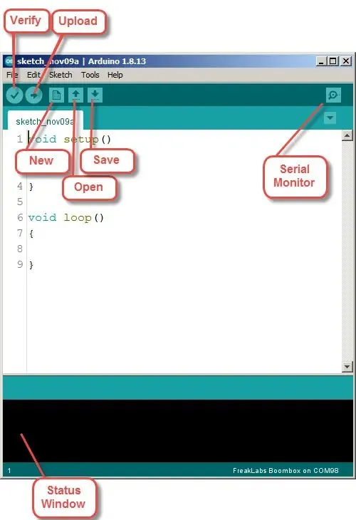 |
 |
Structure Commands:
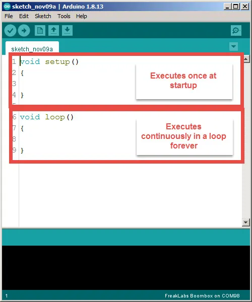
Structure refers to the grammatical rules and organizational elements of the language. This includes the required setup() and loop() functions, as well as the use of curly braces {} to define the beginning and end of a block of code, and semicolons ; to mark the end of a statement. The word void is used to indicate that a function does not return any value to the code that calls it, which would be discussed in later chapters.
- void setup(): This function runs only once, when the board is powered on or reset. It is used to define initial settings, such as specifying whether a pin will be an input or an output.
- void loop(): After the setup() function finishes, the loop() function runs repeatedly, over and over, as long as the board has power. The main instructions for the board's behavior are placed here.
Function Commands:
Functions are blocks of code that perform a specific task. They are executed when they are "called" by name in the sketch.
- pinMode(): This command, used in setup(), defines a specific pin as an INPUT or an OUTPUT. Additionally, an input source can use an internal pull up resistor by INPUT_PULLUP.
- digitalWrite(): This command sets a digital pin to either HIGH (providing voltage, which turns the LED on) or LOW (providing no voltage, which turns it off).
- delay(): This function pauses the program for a specified number of milliseconds. It is used to control the timing of the blink.
- Serial.begin(): This command initiates the serial communication channel. A command speed is Serial.begin(9600) ,which sets the speed of data transfer to 9600 bits per second. It prepares the board to send and receive data.
- Serial.println(): This command sends the text to the computer, the text will then be visible in the Serial Monitor. For example, Serial.println("Hello World").
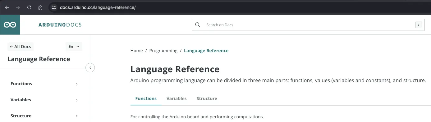
We will learn new Commands each lesson. Click the image and refer to ArduinoDocs for more details.
Blinking an LED
Your first project is to upload a program that makes the onboard LED blink. This LED is a small, square light located near the digital pins on the Arduino Uno board. It is physically connected to digital pin 13. Using this LED allows you to verify that your Arduino is working and that you can successfully upload code without needing any additional components.
You can write the code for this in the Arduino IDE. The core of the sketch uses commands to control the pin and manage timing. Because the onboard LED is connected to pin 13, you will configure that pin as an output in the setup() function. Then, in the loop() function, you use digitalWrite() to turn the LED on and off, with delay() functions in between to create the blinking pattern.
You can write the code for this in the Arduino IDE. The core of the sketch uses commands to control the pin and manage timing. Because the onboard LED is connected to pin 13, you will configure that pin as an output in the setup() function. Then, in the loop() function, you use digitalWrite() to turn the LED on and off, with delay() functions in between to create the blinking pattern.
Blink with Serial Output
// The setup function runs once when you press reset or power the board
void setup() {
  // Initialize the digital pin connected to the LED as an output
  pinMode(LED_BUILTIN, OUTPUT);

  // Start serial communication at 9600 bits per second
  Serial.begin(9600);
}

// The loop function runs over and over again forever
void loop() {
  digitalWrite(LED_BUILTIN, HIGH);  // Turn the LED on
  Serial.println("LED is ON");      // Send message to computer
  delay(1000);                      // Wait for one second

  digitalWrite(LED_BUILTIN, LOW);   // Turn the LED off
  Serial.println("LED is OFF");     // Send message to computer
  delay(1000);                      // Wait for one second
}
Exercise
After you have successfully run the basic blink program, you can modify the code to observe how changes affect the behavior:
- Change the Blink Speed: Try altering the numbers inside the delay() functions. For example, change 1000 to 500 to make the LED blink faster, or to 2000 to make it blink slower. Remember that the number represents milliseconds (1000 milliseconds = 1 second).
- Create an Asymmetric Pattern: Make the LED stay on for a different amount of time than it stays off. For example, try delay(100) after turning the LED on and delay(2000) after turning it off.
- Add Serial Output: Include messages in the Serial Monitor to track the program's progress. Add Serial.begin(9600); to setup() and then add Serial.println("It is too dark, let's turn the LED on!"); and Serial.println("It is too bright, let's turn the LED off!"); after the corresponding digitalWrite commands in the loop(). This will print a message to the computer each time the LED changes state.