Part 1: Hardware
Input - Process - Output
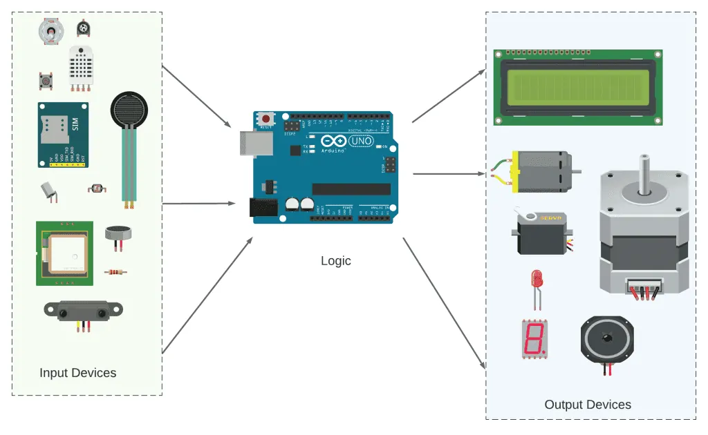
An Arduino system operates on a cycle of input, process, and output. The board first reads a signal from the physical world as an input, typically from a sensor like a button or thermometer. It then performs a process based on the programmed instructions in the sketch, such as comparing the sensor value to a threshold. Finally, it creates an output action, like lighting an LED or starting a motor. This cycle allows the Arduino to sense its environment and respond to it automatically.
 |
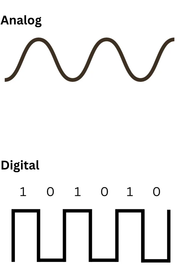 Digital signals have only two discrete states (HIGH/LOW), while analog signals can represent a continuous range of values.
|
|
Input Devices Examples: (Send signals to Arduino)
|
Output Devices Examples: (Controlled by Arduino)
|
The Breadboard
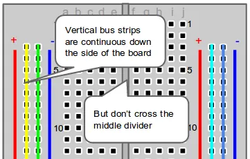
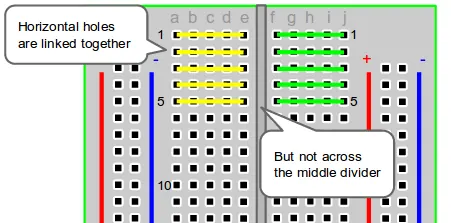
A breadboard is a tool for building temporary electronic circuits without soldering. Its internal structure consists of metal clips arranged in rows and columns beneath the plastic holes. The two outer vertical columns, often marked with red and blue lines, are called power rails. These are typically used for connecting power (5V) and ground (GND). The central area contains horizontal rows of connected clips, separated by a central divider. Components and wires are inserted into these holes to create electrical connections. This design allows for quick circuit modifications and experimentation.
 |
 |
Part 2: Software
We are done with hardware so far, let us equip ourselves with more tools for the up coming tasks, here's a few more software skills.
Variables:
A variable is a named container that stores data. The int data type creates variables that hold integer values (whole numbers from -32,768 to 32,767). Variables allow you to store and modify data throughout your program, making code more readable by using descriptive names instead of repeating numbers.
Variable Assignment: Variables are assigned values using the single equals =, the assignment operator.
Variable Assignment: Variables are assigned values using the single equals =, the assignment operator.
Arduino Pin Declaration
int buttonPin = 2; // Creates a variable storing the value 2
Structure Command:
Comparison Operators: The double equals == operator compares two values and returns true if they are equal, false if they are not. This is used in conditional statements to make decisions.
if-else Statements: Conditional statements is a form of control structure. It allows the program to make decisions and execute different code based on conditions.
if else conditional statement using comparison operator
if (buttonPin != LOW) {
    // Code to run if condition is true
} else {
    // Code to run if condition is false
}
There is a list of comparison operators available:
|
== (equal to)
> (greater than) >= (greater than or equal to) |
< (less than)
<= (less than or equal to) != (not equal to) |
Integrated projects
Basic Button Control
|
This Arduino code implements a basic button-to-LED control system. The setup function configures pin 2 as an input to read a push button and pin 13 as an output to control an LED.
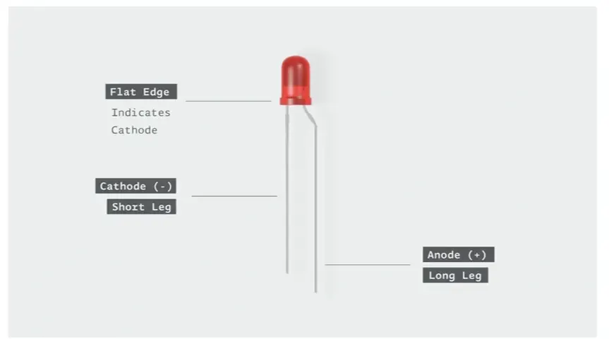
In the main loop, the program continuously monitors the button state - when pressed (reading LOW), the LED turns ON, and when released (reading HIGH), the LED turns OFF. Examine the circuit diagram and follow the flow of the current, from the positive red to the black ground. The two wires on the leds have different lengths:
|
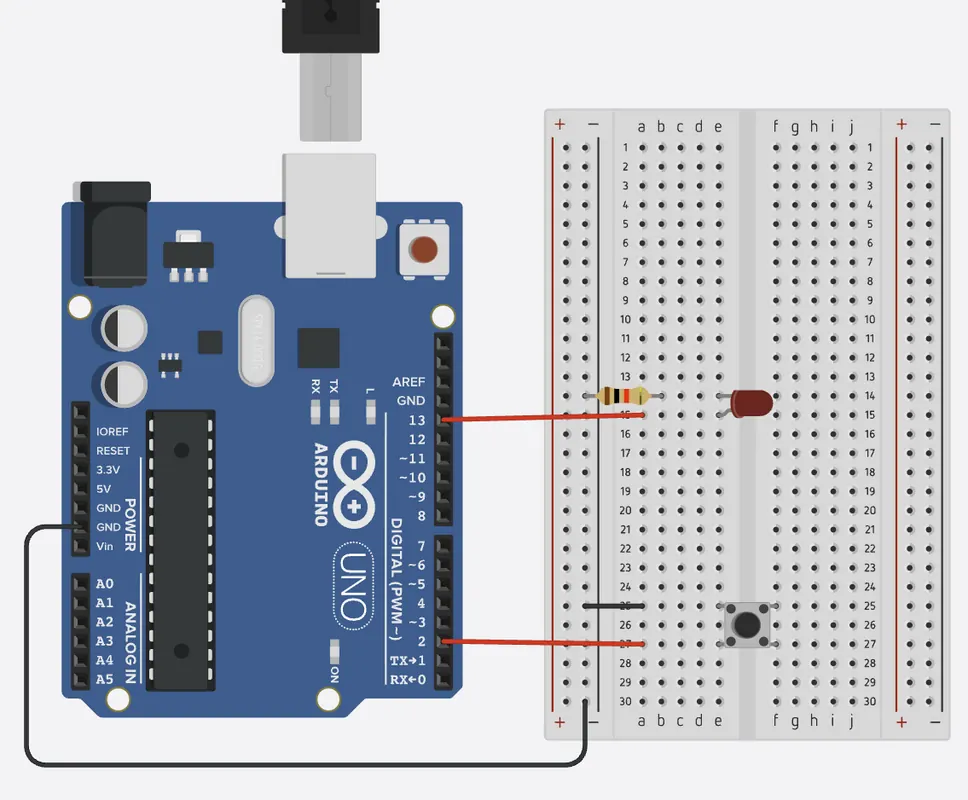 Click the image for interactive simulation.
 |
Basic Button Control
void setup() {
  pinMode(2, INPUT_PULLUP);
  pinMode(13, OUTPUT);
}

void loop() {
  int buttonState = digitalRead(2);

  // Using == operator to compare values
  if (buttonState == LOW) {
    digitalWrite(13, HIGH);  // Turn LED on when button pressed
  } else {
    digitalWrite(13, LOW);   // Turn LED off when button released
  }
}
Exercise 1:
Reverse: Now try to change the setting where the LED turns on when button is not pressed, but turns off when the button is pressed.
Button toggle
In this toggle button exercise, an LED connected to pin 13 changes between on and off states each time a push button connected to pin 2 is pressed. The program uses the `INPUT_PULLUP` mode for the button, which means the pin reads HIGH when the button is released and LOW when pressed. The code tracks both the current and previous button states to detect when the button is first pressed, avoiding repeated triggers from holding the button down. When a press is detected, the LED's state is inverted using the logical NOT operator, creating a toggle effect. This approach allows a momentary push button to function as an on/off switch for the LED.
Button-Controlled LED Toggle
const int buttonPin = 2;
const int ledPin = 13;

int buttonState;
int lastButtonState = HIGH;
int ledState = LOW;

void setup() {
  pinMode(buttonPin, INPUT_PULLUP);
  pinMode(ledPin, OUTPUT);
  digitalWrite(ledPin, ledState);
}

void loop() {
  buttonState = digitalRead(buttonPin);

  if (buttonState == LOW && lastButtonState == HIGH) {
    ledState = !ledState;
    digitalWrite(ledPin, ledState);
    delay(50);
  }

  lastButtonState = buttonState;
  delay(10);
}
Exercise 2:
More LEDs: Add another LED to pin 12, such that it is always at opposite state compare to led at pin 13.